As I continue my journey with STM32 development, I wanted to share my findings with how to get a Virtual COM Port (VCP) working with a Nucleo board.
Specifically, I’m using the Nucleo-F042K6, as it has a built-in USB device peripheral (full speed), and it does not require an external crystal. I highly recommend looking over the USB Hardware and PCB Guidelines document from ST Microelectronics to learn about what’s needed for your particular STM32 part. Note that if you are using a Nucleo board with an STM32F401 or STM32F411, you will need to solder an external crystal to the board, as it is unpopulated on those boards.
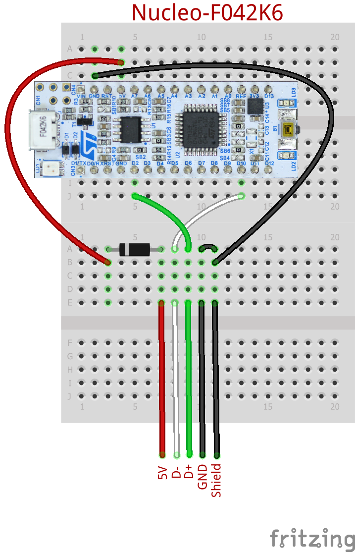
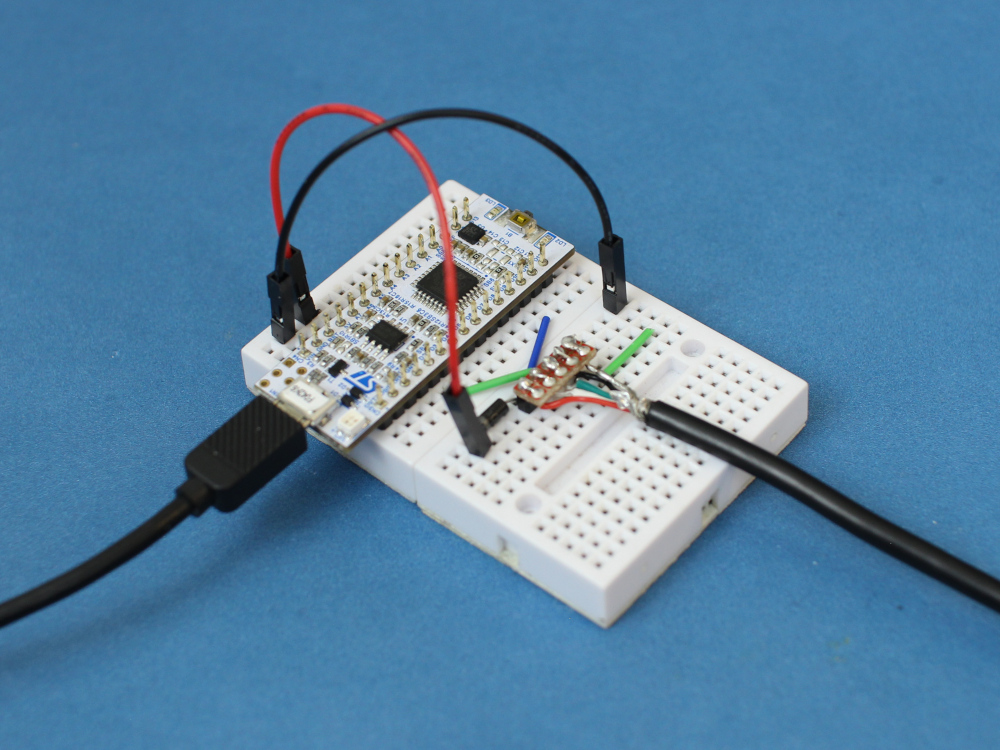
To begin, strip a USB cable or get a USB breakout board (like this one from SparkFun) and connect the lines to a breadboard as shown in the Fritzing diagram below. Make the following connections:
- VUSB → Diode → Nucleo 5V (don’t want to short something if we’re plugging in 2 USB cables!)
- USB D- → Nucleo D10 (PA11)
- USB D+ → Nucleo D2 (PA12)
- USB GND → Nucleo GND
- USB GND → USB Shield (don’t know if this is necessary, but it makes me feel better)
Also, this is super important: remove the jumper that comes default on your Nucleo board! It bridges D2 and GND and will short out our D+ line if left in place.
Plug the two USB cables from the Nucleo board into your computer. We’ll be sending our compiled program over to the ST-LINK side of the board, and the VCP will enumerate on the USB lines that we just added. I don’t have a bootloader working (yet) to where we can send binary files over VCP, but that’s on my to-do list.
For this, I’m using STM32CubeIDE along with the STM32F0 HAL API.
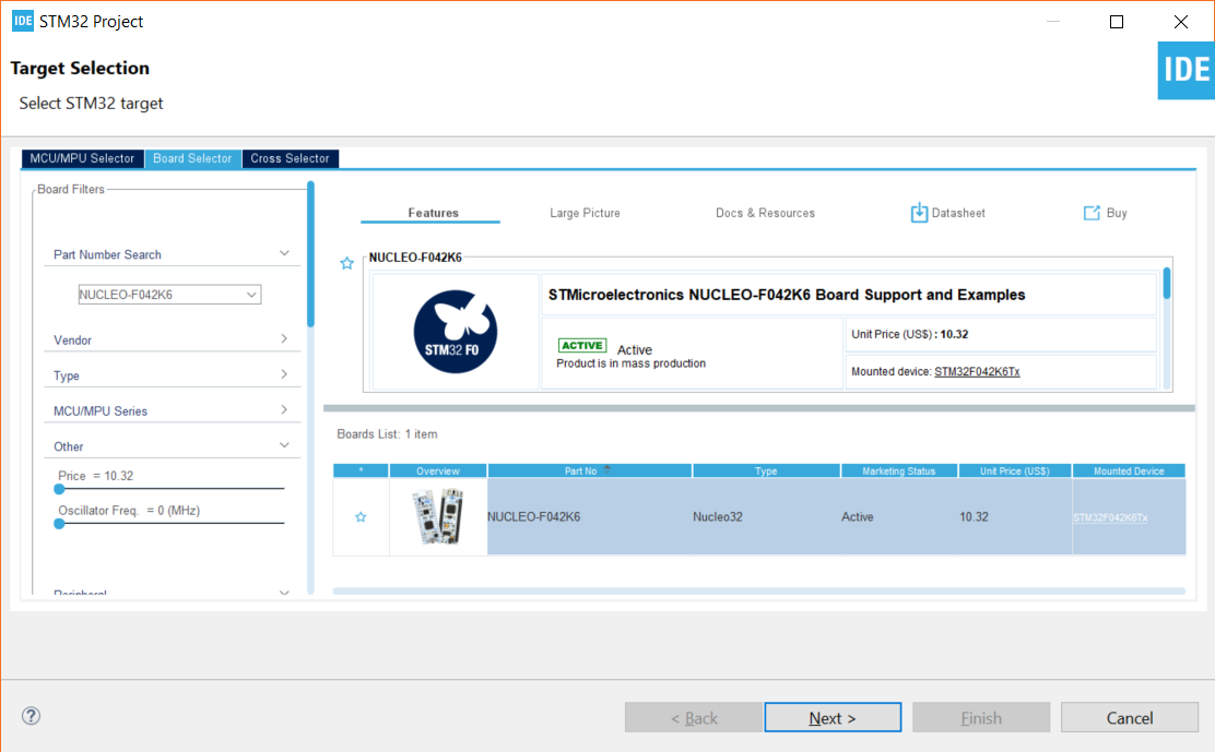
In STM32CubeIDE, start a new project (File > New > STM32 Project). Choose your part or board. I’ll pick the Nucleo-F042K6, since that’s the board I have.
On the next screen, give your project a useful name (such as “nucleo-f042k6-vcp-test”). Leave everything else as default. We’ll be using C as our language for this example. Click Finish, and you’ll be asked a few questions:
- Yes to “initialize all peripherals with their default Mode”
- Yes to “open this perspective now”
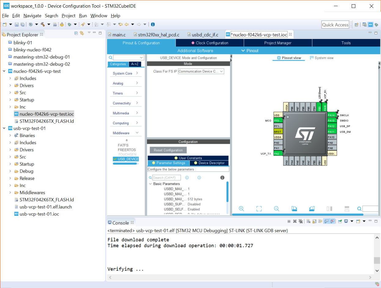
In the CubeMX configuration perspective, you’ll need to enable a few options to initialize the USB as a Virtual COM Port. In the Pinout & Configuration tab, go to Categories > Connectivity and click USB. Enable Device (FS). You should see PA11 and PA12 be automatically configured for USB_DM and USB_DP.
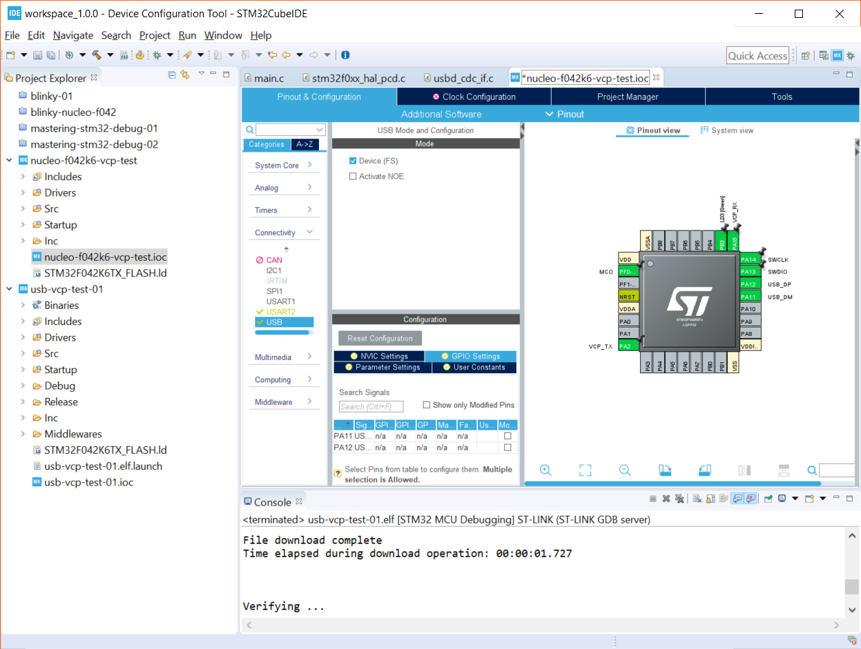
Under Categories > Middleware, select USB_DEVICE. Change Class For FS IP to Communication Device Class (CDC). This tells the USB stack that we want to enumerate as a CDC device, which will allow us to send serial data to and from our computer across the USB lines.
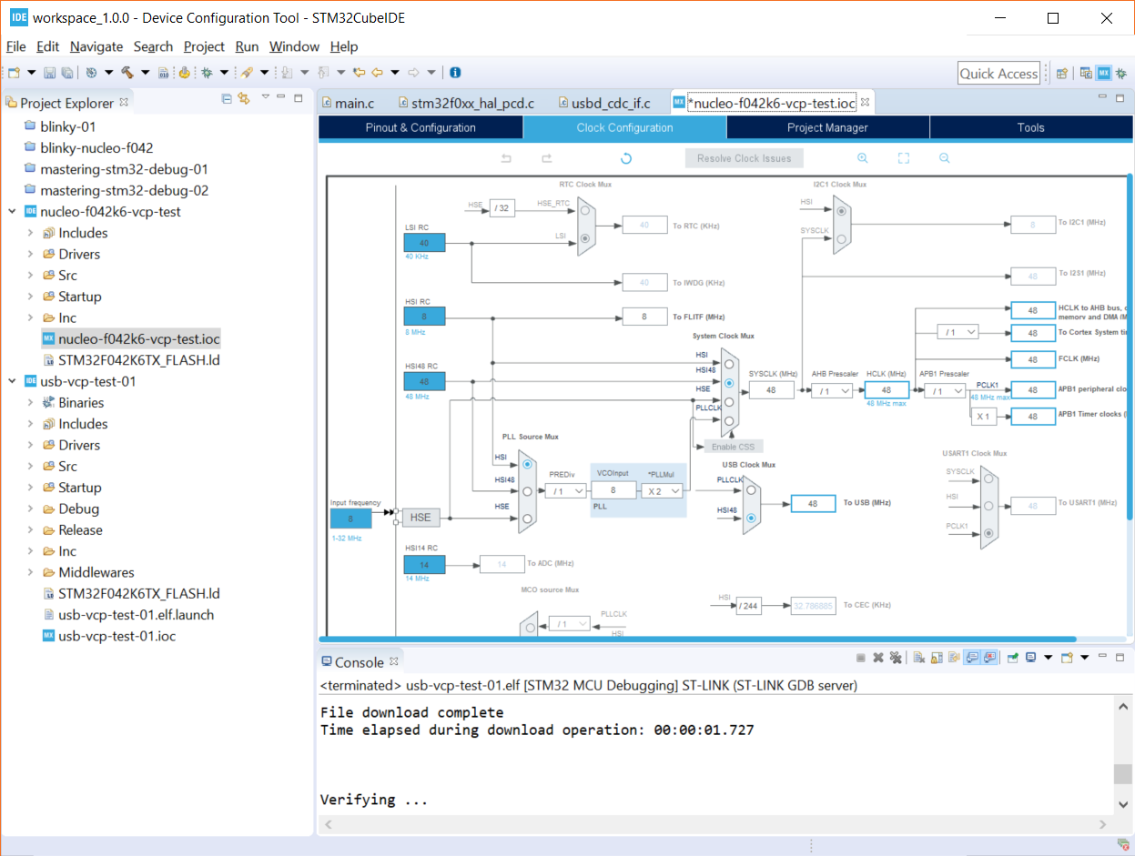
Click on the Clock Configuration tab. The software will tell you that your clocks have issues. By default, the Nucleo-F042K6 board is configured for 8 MHz clocks for almost everything. We need to bump those up to 48 MHz for USB to work. Luckily, you can just click Yes on the pop-up when asked to run the automatic clock issues solver. This should automatically change all of the necessary clocks to 48 MHz.
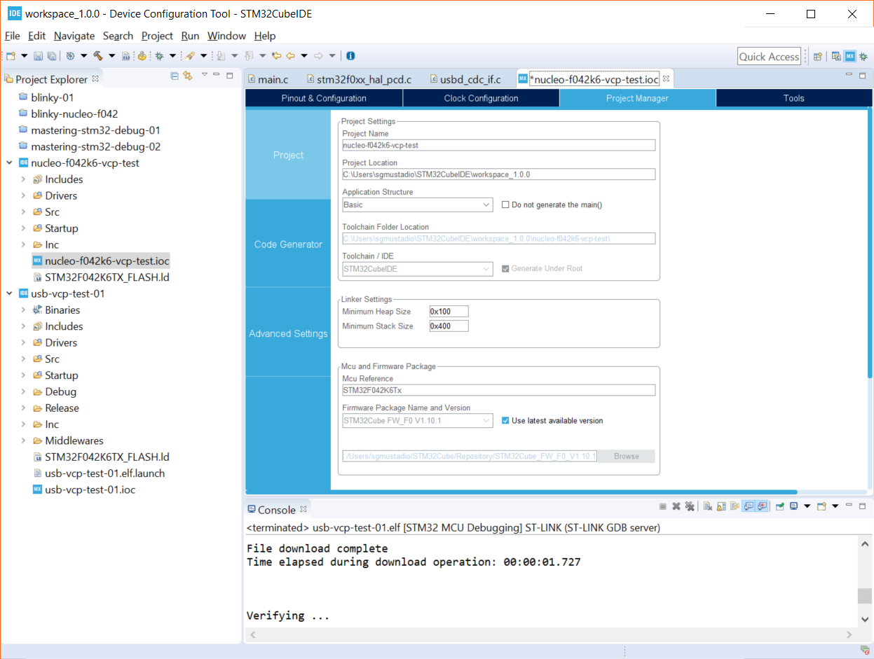
In the Project Manager tab, change the Minimum Heap Size to 0x100. The STM32F042K6 comes with 6 kB of RAM, which isn’t a whole lot. USB functionality takes up probably 2-3 kB worth of that memory, so we need to be careful about how we use the rest.
We can free up some space by adjusting the minimum heap and stack sizes. These parameters essentially reserve sections of data memory for the heap and stack. By setting 0x200 and 0x400, we’ve told the processor to reserve 1 kB of RAM for the heap and stack, respectively. We need to lower one of them in order to accommodate the USB functions. I chose heap, as it seems less likely we’ll be using dynamically allocated memory for this application.
If you get an error message like `._user_heap_stack’ will not fit in region `RAM’ or region `RAM’ overflowed by 64 bytes when you compile, it means you are running out of RAM in your application. You will need to go into the Device Configuration Tool (the .ioc file) and adjust the stack and heap settings as described above. Alternatively, you can go into the .ld linker script and look for the _Min_Heap_Size and _Min_Stack_Size settings there (just know that this file will be overwritten if you make changes in the graphical Device Configuration Tool).
Click File > Save to save the changes to the CubeMX configuration. You’ll be asked if you want to generate Code. Click Yes.
In your project files, navigate to the Src directory. Notice that you have several USB-related files that have been added. usbd_cdc_if.c contains the functions that allow us to send and receive serial data using the USB Communication Device Class. Feel free to peek in there, if you wish.
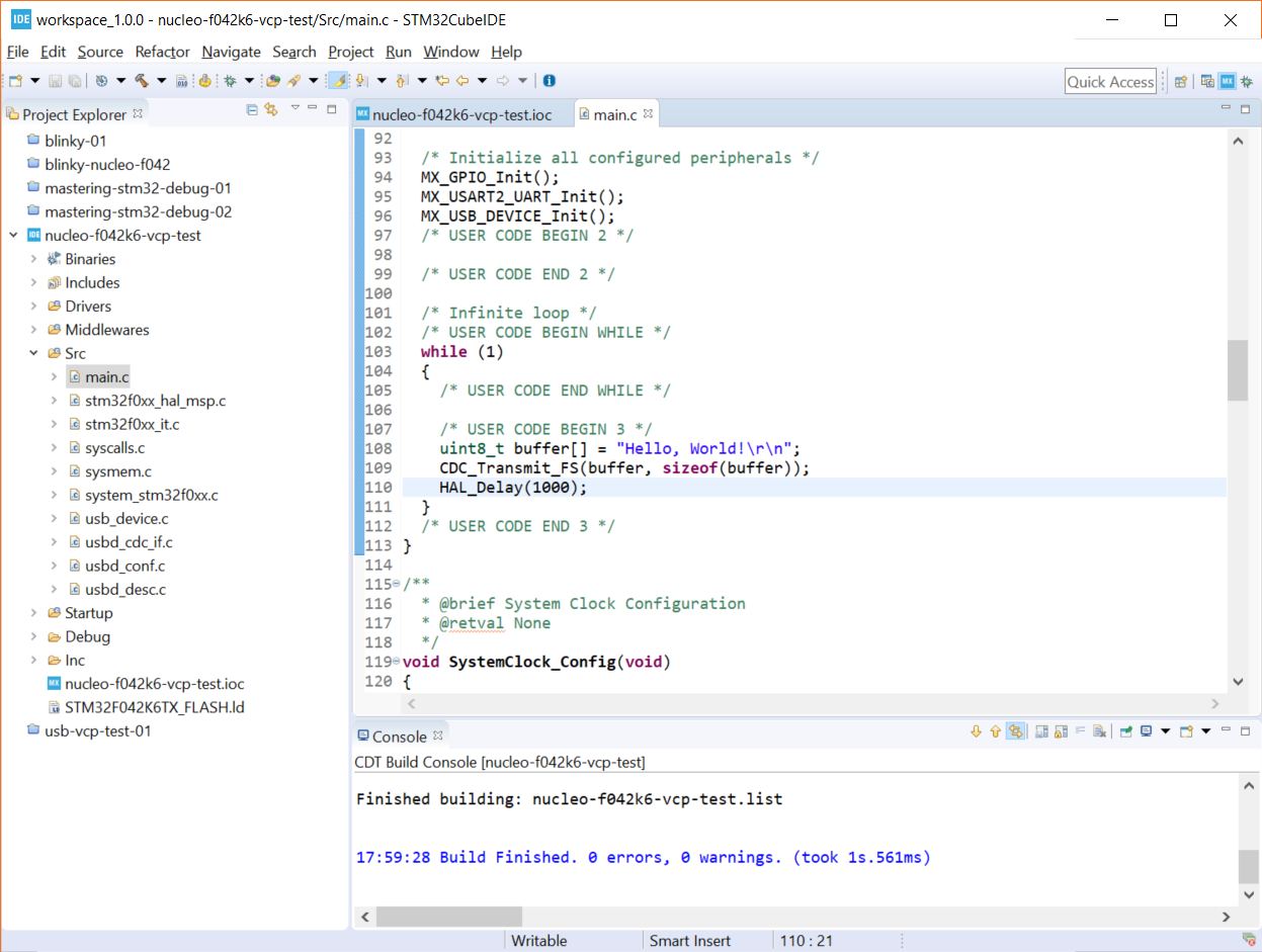
Open up Src > main.c. At the top, under /* USER CODE BEGIN Includes */ , enter the following line:
#include "usbd_cdc_if.h"
This will let us call functions from the CDC library. Scroll down to our while(1) loop in main. Under /* USER CODE BEGIN 3 */ (but still inside the while loop), enter the following:
uint8_t buffer[] = "Hello, World!\r\n";
CDC_Transmit_FS(buffer, sizeof(buffer));
HAL_Delay(1000);
Here, we create a simple string and call a USB CDC function to send out that string over the USB lines. We then wait for 1 second before repeating this action ad infinitum.
Click Project > Build All to build the project. Click Run > Debug As > STM32 MCU C/C++ Application. A pop-up window will appear asking you to create a new launch configuration. Note that if you are not using a Nucleo board or an ST-LINK, you can change the hardware debugger (e.g. to a Segger J-LINK) in the Debugger tab. If you are using a Nucleo, leave everything as default and click OK.
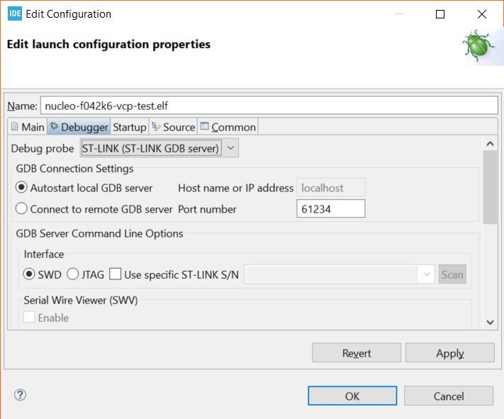
If asked to switch to the Debug perspective, click Switch. When the new perspective opens, click Run > Resume (or the play button on the toolbar).
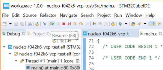
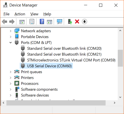
Your code should now be running, and the microcontroller will enumerate as a USB device! Feel free to verify the new serial port in your OS’s device manager. This should show up as a USB serial or COM port.
Open your favorite serial terminal program, and enter the following connection details:
- Port: USB serial or COM port discovered above
- Baud rate: 9600
- Data bits: 8 (default)
- Parity: None (default)
- Stop bits: 1 (default)
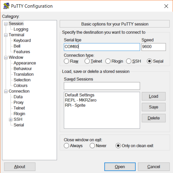
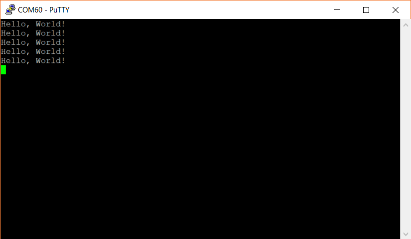
Open the serial connection, and you should be greeted by that oh-so-familiar phrase, repeating over and over again:
When you’ve had enough strings, feel free to press the stop button in the IDE to stop the program from running on the STM32.
Interestingly enough, the STM32 seems to support autobaud detection by default. Try changing the serial terminal’s baudrate to anything else and see if you can still receive text. I bet that disabling autobaud would save some RAM, but I have not discovered how yet.
From what I understand, CDC_Receive_FS() is a callback, so you’ll need to change its definition in usbd_cdc_if.c to get it to work. I haven’t played with it yet, so that’ll be a post for another time.
I hope that this helps you get started with your STM32 USB journey!
Hello,
>Interestingly enough, the STM32 seems to support autobaud detection by default.
Well, this is a “virtual UART”, at least for the PC. Meaning, that data is directly send between the PC and the MCU. Since there is no UART involved, the settings are meaningless.
https://www.st.com/content/ccc/resource/technical/document/user_manual/cf/38/e5/b5/dd/1d/4c/09/DM00108129.pdf/files/DM00108129.pdf/jcr:content/translations/en.DM00108129.pdf
And for context:
https://rfc1149.net/blog/2013/03/05/what-is-the-difference-between-devttyusbx-and-devttyacmx/
> From what I understand, CDC_Receive_FS() is a callback, so you’ll need to change its definition in usbd_cdc_if.c to get it to work.
Well, you have get the data, stored in the “UserTxBufferFS[APP_TX_DATA_SIZE]” variable out, or interpret the data, because after this function returns, the next USB data package is allowed in and the data might be overridden…
Good to know, thank you! I’m definitely still learning this stuff 🙂
Hi Shawn. thanks for this. im terrible at firmware, but just so you know, im a hardware guy thru & thru.
if you are using two USB ports for this on the same machine, you can leave the +5v Vbus disconnected… it works fine here without sending the “nucleo 5v” back into the 2nd port . For USB peripherals typically acting as slaves you dont need to provide a Vbus connection, if that makes sense.
The diode would created more issues that it solves…
Good to know, thanks!
Thank you so much for this helping material 🙂
Thank you man god bless you.
Hi Shawn,
I have tried to configure USB in CDC mode using STM32L4R5ZI MCU.
Unfortunately the my device is not detected when connected to PC.
Can you please guide me to identify the issue.
Regards,
Rajesh K.
I’ve also been having issues getting CDC working on the L4 chips. I’ll let you know if I figure it out.
Thanks for your tutorials. They were inspiration that helped me make the transition from Arduino to STM32!
I did get USB receiver working. The middleware and USB stack are not consistent afrom one series of STM32 to another. A bit of adjustment is needed.
With the Nucleo-L476 board you need to activate the ceramic resonator in the RCC to stabilize the LSE. 32 kHz oscillator that stabilizes the MSI clock via a phase locked loop. this then used to provide a precise 48 MHz to the USB peripheral. This is not done by default. A trick to doing this is to activate the RTC..Then the ceramic resonator can be selected. I just set the RTC to “activate clock source”. Then I could select the LSE in the clock configuration menu. Getting the clock right is essential as the default LSI RC does not have the stability to run USB receive. In my humble opinion a proper crystal would be better in LSE as watch crystals are 32 768;Hz and for reasons I will not go into, the stability of all crystals oscillators is best at this frequency.
in connectivity under pin configuration select USB_OTG_FS and under middleware “USB_DEVICE”. I use default settings. Select,USB device and class CDC.
USB receive needs the Line coding buffer received in CDC_SET_LINE coding returned in CDC_GET_LINE_CODING. It’s 7 bytes long in usb_cdc_if.c
The data need to be extracted from the buffer in CDC_Received_FS in the same file. The length of the data in Buf is in Len. afterwards use memset(Buf,0x00, byte no) to clear the buffer. You can manipulate the data in this subroutine. This routine is an interrupt callback and new data cannot be loaded until return from this routine. The blocking is done by sending a NAK against any received packets on the USB bus so processing is held up while the data is parsed.
In my application I simply read a character string where the strlen(…) function is used to test if any data needs to be read in a nonblocking way.
All in all, it is not easy to get going as the USB transmit examples.
I hope this is of some help for STM32L users.
Harry W.
Awesome, thank you!
I was having the device not recognised problem – Harry’s changes rectified the problem for me
Hi! What frequency crystal oscillator would I need if I want to use the STM32401RE?
I don’t think it matters exactly what value oscillator you use so long as A) the 401RE supports it and B) you can get the clock dividers/PLL to ultimately give you 48 MHz on the USB clock.
That’s interesting what you said about the stack and the heap. In the STM32 USB Training videos on YouTube the guy said to allocate 0x600 for the heap for USB CDC data structures. I’m no expert so can’t say which is correct, I suppose it is implementation dependent too.
Interesting…if I remember correctly, the USB CDC libraries take up more stack space, so I lowered my minimum required heap to allow the stack to grow. This only seems to be required for devices with very little memory, like the F042 series. If you’re working with more memory, you probably have a lot more wiggle room in the amount of minimum heap/stack you can set.
Hi Shawn, thanks for this. The CubeIDE configurator doesn’t actually warn you about the SYSCLK being under-clocked for the STM32H7 USB so this was extremely helpful for a very annoying problem!
Glad it helped!
One note when you’re using a Nucleo board (I have a Nucleo-L432): You can use the USB port already used for programming also for communication. The schematics show UART2 pins are used as VCP_RX and VCP_TX which are multiplexed or passed-through in the onboard ST-Link. The solution here on this page seems to cause many troubles on my system when you reset the device or re-program the device then the USB port also stops working. The communication with the VCP through the programming port however works after you programmed the device even without disconnecting the terminal software. 😉
Thanks for the heads up. I’ve been using the UART connection through the STLINK portion of the Nucleo boards for 99% of my debugging/serial out–it works really well. I wrote this post for anyone curious about how to set up native USB on some of the Nucleo boards (and VCP is a good way to test that).
This was very helpful in verifying that USB device mode does actually work on this STM32WB nucleo board, after ST’s example code does… not. Very straightforward!
can you please do a tutorial using the CDC_Receive_FS() please !!!!
I am super super super grateful to you.
Coming from arduino to this as a full stack web developer, Your tutorial went over the main points very well.
Any progress I make in stm32 world can be laid down at your feet.
Thanks for giving a idiot proof tutorial.
Hope for more in the future
Thank you very much for your help
Thanks so much for this.
This is a great walk-through for use of the non-intuitive STCubeMX tool, and I had been struggling to get USB CDC working for weeks with ST’s own examples on my STM32F429 Nucleo board. This works no problems, and is a lovely example.
Now I’ll have a go at getting the Rx side going with the callback…
Also the directions are simple, unambiguous and easy to follow – this is not as easy to do as it appears! Well done, and thanks for this excellent article!
Rich
Glad it helped!
Thank you for this
Great step by step info, I had problems with “usb device descriptor failed” and came on some info on pcbartists website
What to do :
Check clock config (right crystal speed, HSE activated and 45Mhz USB)
Enable in USB_DRD_FS the global interrupts >> this one was the big one for me
I can now enjoy my STM32G0 !
Thanks for the info about how to fix that device descriptor issue!
on NUCLEO-L432KC (https://www.st.com/en/evaluation-tools/nucleo-l432kc.html)
USART2 is pre-connected to the virtual com port of the USB-debug-connector (CN1
ST-LINK Micro B USB connector) see page 20 of https://www.st.com/resource/en/user_manual/um1956-stm32-nucleo32-boards-mb1180-stmicroelectronics.pdf
You can open a serial terminal on /dev/tty.usbmodem3302 (MOX; with Linux and Windows it might be called differtly) with the same baud rate configured like in Your project / hardware (*.ioc File) and then send and receive serial data to the STM32L432KC MCU. With 9600 baud/s 8N1 it runns well, other speeds I did not test.
Best regards, Peter
Thanks for the helpful information.
Do you know if it’s possible to power the device through the USB breakout board?
Thanks
Fred said: Enable in USB_DRD_FS the global interrupts >> this one was the big one for me
tl;dr: I found that in the latest (as of today) STM32CubeMX v6.17.0, when enabling USB_DRD_FS, the NVIC interrupt is somehow not enabled by default.
Using the Device CDC middleware, I got the following in my Linux syslog as host:
kernel: usb 3-6.3: new full-speed USB device number 29 using xhci_hcd
kernel: usb 3-6.3: device descriptor read/64, error -32
kernel: usb 3-6.3: device descriptor read/64, error -32
kernel: usb 3-6.3: new full-speed USB device number 30 using xhci_hcd
kernel: usb 3-6.3: device descriptor read/64, error -32
kernel: usb 3-6.3: device descriptor read/64, error -32
kernel: usb 3-6-port3: attempt power cycle
kernel: usb 3-6.3: new full-speed USB device number 31 using xhci_hcd
kernel: usb 3-6.3: Device not responding to setup address.
kernel: usb 3-6.3: Device not responding to setup address.
kernel: usb 3-6.3: device not accepting address 31, error -71
kernel: usb 3-6.3: WARN: invalid context state for evaluate context command.
kernel: usb 3-6.3: new full-speed USB device number 32 using xhci_hcd
kernel: usb 3-6.3: Device not responding to setup address.
kernel: usb 3-6.3: Device not responding to setup address.
kernel: usb 3-6.3: device not accepting address 32, error -71
kernel: usb 3-6.3: WARN: invalid context state for evaluate context command.
kernel: usb 3-6-port3: unable to enumerate USB device
I fought for ages trying to figure out if it was a clock issue, some problem on my (sw) side, or whatever, until I read somewhere that interrupts have to be enabled, and at some point I innocently clicked on the NVIC Settings tab on the USB_DRD_FS Connectivity tab, and there it was: the interrupt was not enabled by default.
After enabling this interrupt and re-generating code, I got my Nucleo-G0B1RE board’s on-board USB Virtual port working.
Then I came *back* to your write up (thanks!) and saw Fred’s message lol