Programming
Is Embedded Rust Ready for Primetime?

Is Embedded Rust Ready for Primetime?
Opinion
February 24, 2026
The Hidden Costs of Using Zephyr (and How to Mitigate Them)

The Hidden Costs of Using Zephyr (and How to Mitigate Them)
Opinion
February 17, 2026
The Difference Between a Hobbyist and a Hirable Embedded Systems Engineer

The Difference Between a Hobbyist and a Hirable Embedded Systems Engineer
Opinion
February 10, 2026
How Long It Actually Takes to Become Productive with a New Microcontroller

How Long It Actually Takes to Become Productive with a New Microcontroller
Opinion
January 20, 2026

How Interruptions Destroy Focus: What Neuroscience Says About Deep Work, Productivity, and Learning

How Interruptions Destroy Focus: What Neuroscience Says About Deep Work, Productivity, and Learning
Opinion
December 9, 2025
How to Use the Mosquitto MQTT Broker (With SSL/TLS)

How to Use the Mosquitto MQTT Broker (With SSL/TLS)
Tutorial
December 2, 2025
How to Use the Command Line (CLI) With the Arduino UNO Q

How to Use the Command Line (CLI) With the Arduino UNO Q
Tutorial
November 25, 2025
Embedded Rust Workshop: Reflections from Hackaday Supercon

Embedded Rust Workshop: Reflections from Hackaday Supercon
Opinion
November 11, 2025
ESP32 – How to Perform an HTTP GET Request with ESP-IDF
ESP32 – How to Perform an HTTP GET Request with ESP-IDF
Tutorial
October 21, 2025
How to Get a Job in Edge AI: Essential Skills for 2025
How to Get a Job in Edge AI: Essential Skills for 2025
Opinion
October 14, 2025
ESP32 – Creating a WiFi Driver with ESP-IDF
ESP32 – Creating a WiFi Driver with ESP-IDF
Tutorial
October 7, 2025
ESP32 – How to Use Kconfig with ESP-IDF
ESP32 – How to Use Kconfig with ESP-IDF
Tutorial
September 9, 2025
When to Use an RTOS: An Important Decision for Embedded Projects
When to Use an RTOS: An Important Decision for Embedded Projects
Opinion
September 2, 2025
ESP32 – How to Use CMake with ESP-IDF
ESP32 – How to Use CMake with ESP-IDF
Tutorial
August 26, 2025
ByteGrader: An Open Source, Modular Autograder for Embedded Systems (and Beyond)

ByteGrader: An Open Source, Modular Autograder for Embedded Systems (and Beyond)
Project
August 5, 2025
Monitoring Stack and Heap Usage in Zephyr: How to Detect Memory Leaks

Monitoring Stack and Heap Usage in Zephyr: How to Detect Memory Leaks
Tutorial
July 15, 2025
Staying Current with Embedded Systems Tools, Languages, and Frameworks Without Getting Overwhelmed

Staying Current with Embedded Systems Tools, Languages, and Frameworks Without Getting Overwhelmed
Opinion
July 8, 2025
How to Run an ESP32 Zephyr Application on Espressif’s QEMU

How to Run an ESP32 Zephyr Application on Espressif’s QEMU
Tutorial
July 1, 2025
How to Present Your Upskilling Journey to Land a Senior Embedded Role

How to Present Your Upskilling Journey to Land a Senior Embedded Role
Opinion
June 24, 2025

How to Learn Embedded Systems While Working Full-Time: Lessons from an Amazon Robotics Engineer

How to Learn Embedded Systems While Working Full-Time: Lessons from an Amazon Robotics Engineer
Personal
June 10, 2025
The Wrong Way to Use AI (and How to Actually Write Better Code with LLMs)

The Wrong Way to Use AI (and How to Actually Write Better Code with LLMs)
Opinion
June 3, 2025
Why Use Zephyr? A Practical Guide for Embedded Engineers Choosing the Right RTOS

Why Use Zephyr? A Practical Guide for Embedded Engineers Choosing the Right RTOS
Opinion
May 27, 2025
How to Create a Web Server (with WebSockets) Using an ESP32 in Arduino
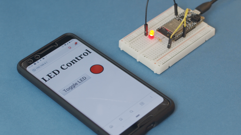
How to Create a Web Server (with WebSockets) Using an ESP32 in Arduino
Tutorial
September 9, 2019
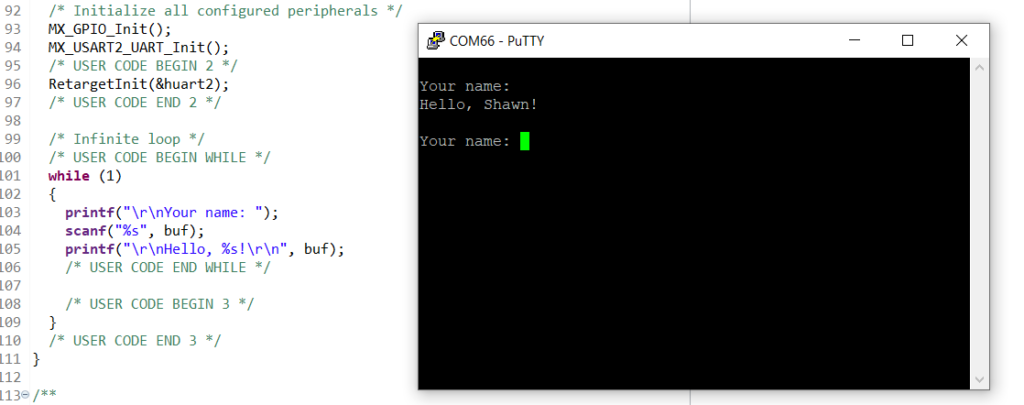
Getting Started with STM32 Nucleo USB (Virtual Com Port)
Getting Started with STM32 Nucleo USB (Virtual Com Port)
Tutorial
June 16, 2019
Arduino Zero (SAMD21) FDPLL with CMSIS
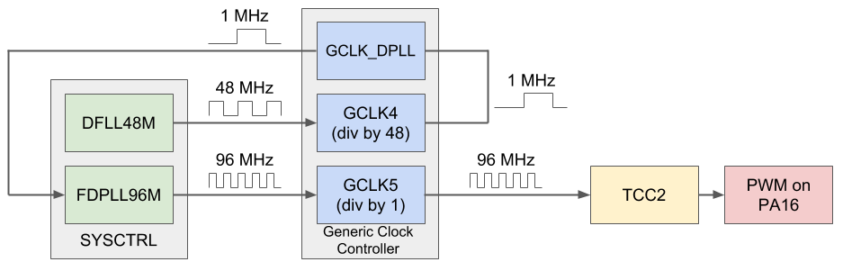
Arduino Zero (SAMD21) FDPLL with CMSIS
Tutorial
December 27, 2018
Arduino Zero (SAMD21) Raw PWM Using CMSIS
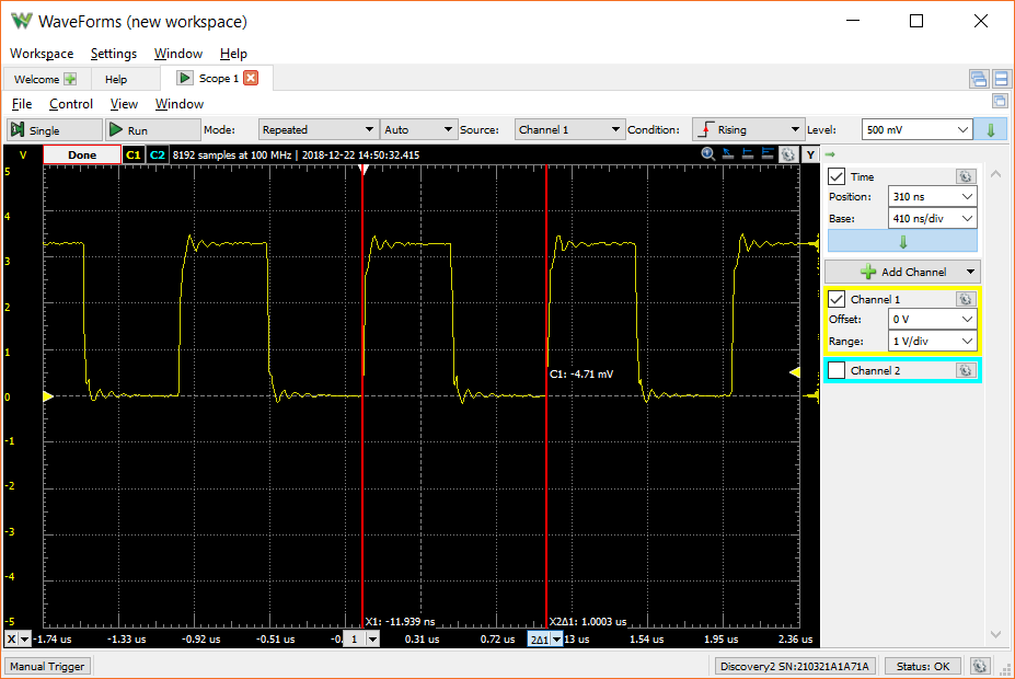
Arduino Zero (SAMD21) Raw PWM Using CMSIS
Tutorial
December 22, 2018
Learning the Teensy LC: Interrupt Service Routines
Learning the Teensy LC: Interrupt Service Routines
Tutorial
May 17, 2015

