Tutorial
How to Use the Mosquitto MQTT Broker (With SSL/TLS)

How to Use the Mosquitto MQTT Broker (With SSL/TLS)
Tutorial
December 2, 2025
How to Use the Command Line (CLI) With the Arduino UNO Q

How to Use the Command Line (CLI) With the Arduino UNO Q
Tutorial
November 25, 2025
What Is Transport Layer Security (TLS)?
What Is Transport Layer Security (TLS)?
Tutorial
November 4, 2025
ESP32 – How to Perform an HTTP GET Request with ESP-IDF
ESP32 – How to Perform an HTTP GET Request with ESP-IDF
Tutorial
October 21, 2025
ESP32 – Creating a WiFi Driver with ESP-IDF
ESP32 – Creating a WiFi Driver with ESP-IDF
Tutorial
October 7, 2025
ESP32 – How to Use Kconfig with ESP-IDF
ESP32 – How to Use Kconfig with ESP-IDF
Tutorial
September 9, 2025
ESP32 – How to Use CMake with ESP-IDF
ESP32 – How to Use CMake with ESP-IDF
Tutorial
August 26, 2025
Monitoring Stack and Heap Usage in Zephyr: How to Detect Memory Leaks

Monitoring Stack and Heap Usage in Zephyr: How to Detect Memory Leaks
Tutorial
July 15, 2025
How to Run an ESP32 Zephyr Application on Espressif’s QEMU

How to Run an ESP32 Zephyr Application on Espressif’s QEMU
Tutorial
July 1, 2025
Getting Started with NVIDIA Jetson Orin Nano
Getting Started with NVIDIA Jetson Orin Nano
Tutorial
June 4, 2024
How to Build OpenOCD and Picotool for the Raspberry Pi Pico on Windows
How to Build OpenOCD and Picotool for the Raspberry Pi Pico on Windows
Tutorial
April 18, 2021
How to Set Up Raspberry Pi Pico C/C++ Toolchain on Windows with VS Code
How to Set Up Raspberry Pi Pico C/C++ Toolchain on Windows with VS Code
Tutorial
April 9, 2021
Custom Wake Word Part 1: Capturing Data

Custom Wake Word Part 1: Capturing Data
Tutorial
July 1, 2020
How to Install TensorFlow with GPU Support on Windows
How to Install TensorFlow with GPU Support on Windows
Tutorial
June 17, 2020
How to Create a Web Server (with WebSockets) Using an ESP32 in Arduino
How to Create a Web Server (with WebSockets) Using an ESP32 in Arduino
Tutorial
September 9, 2019
Getting Started with STM32 Nucleo USB (Virtual Com Port)
Getting Started with STM32 Nucleo USB (Virtual Com Port)
Tutorial
June 16, 2019
Arduino Zero (SAMD21) FDPLL with CMSIS
Arduino Zero (SAMD21) FDPLL with CMSIS
Tutorial
December 27, 2018
Arduino Zero (SAMD21) Raw PWM Using CMSIS
Arduino Zero (SAMD21) Raw PWM Using CMSIS
Tutorial
December 22, 2018
Arduino WebSocket Server Using an ESP32

Arduino WebSocket Server Using an ESP32
Tutorial
November 1, 2018
Getting Started with Phaser Part 3: Sprites and Movement
Getting Started with Phaser Part 3: Sprites and Movement
Tutorial
July 5, 2016
Getting Started with Phaser Part 2: Drawing Text
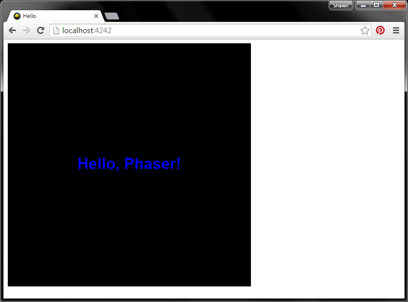
Getting Started with Phaser Part 2: Drawing Text
Tutorial
June 26, 2016
Getting Started with Phaser Part 1: Web Server

Getting Started with Phaser Part 1: Web Server
Tutorial
April 14, 2016
Getting Started with EasyEDA Part 3: PCB Layout
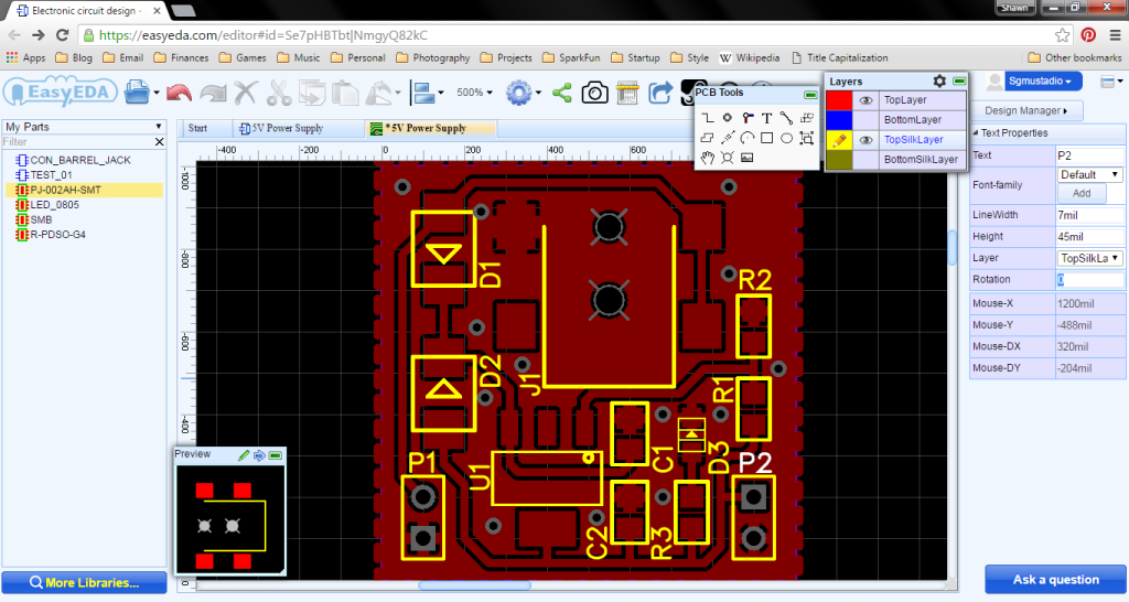
Getting Started with EasyEDA Part 3: PCB Layout
Tutorial
March 27, 2016
Getting Started with EasyEDA Part 2: Schematic Capture
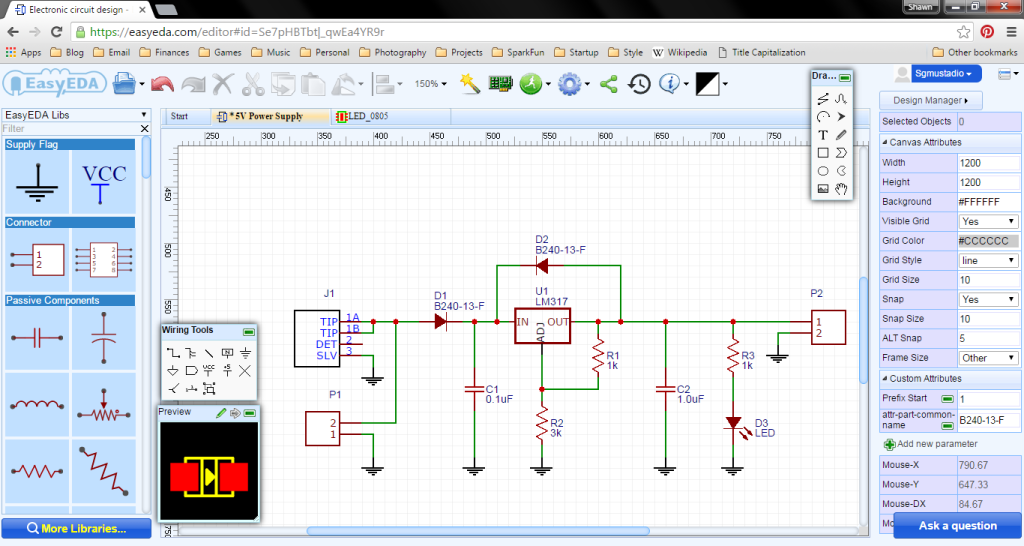
Getting Started with EasyEDA Part 2: Schematic Capture
Tutorial
March 26, 2016
Getting Started with EasyEDA Part 1: Part Creation
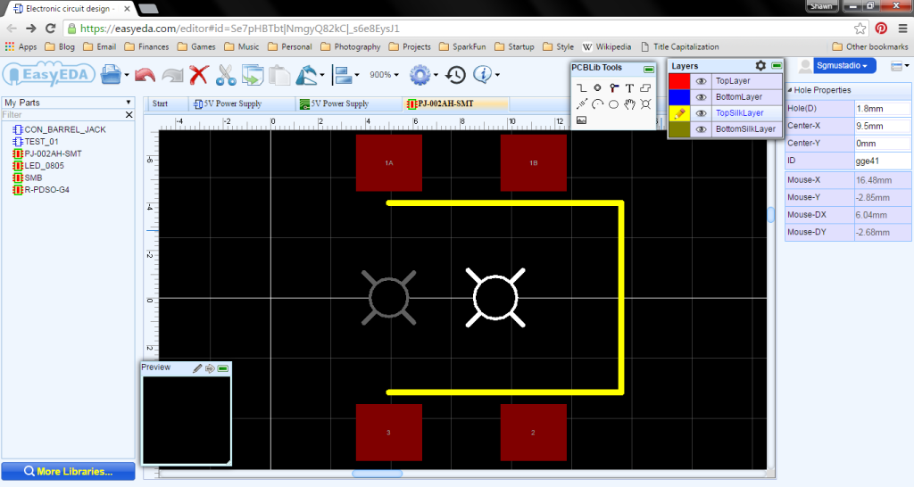
Getting Started with EasyEDA Part 1: Part Creation
Tutorial
March 25, 2016
Cross Compiling on Linux for the Edison
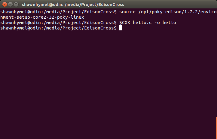
Cross Compiling on Linux for the Edison
Tutorial
February 11, 2016
Writing Your Own UPM Module: Getting Started

Writing Your Own UPM Module: Getting Started
Tutorial
December 31, 2015
Creating a Custom Linux Kernel for the Edison (release 2.1)
Creating a Custom Linux Kernel for the Edison (release 2.1)
Tutorial
December 20, 2015
Bluetooth Low Energy Peripherals with JavaScript
Bluetooth Low Energy Peripherals with JavaScript
Tutorial
November 22, 2015
Quick Tip: HTTP GET with the ESP8266 Thing
Quick Tip: HTTP GET with the ESP8266 Thing
Tutorial
September 16, 2015
Learning the Teensy LC: Interrupt Service Routines
Learning the Teensy LC: Interrupt Service Routines
Tutorial
May 17, 2015
Using Python and BLE to Receive Data from the RFduino
Using Python and BLE to Receive Data from the RFduino
Tutorial
May 15, 2015

Quick Tip: Reading Fuse Bits in an Arduino
Quick Tip: Reading Fuse Bits in an Arduino
Tutorial
January 22, 2015
Creating a Custom Linux Kernel for the Edison
Creating a Custom Linux Kernel for the Edison
Tutorial
December 21, 2014
Quick Tip: Changing Default Directory of Git Bash
Quick Tip: Changing Default Directory of Git Bash
Tutorial
December 9, 2014
Getting Started With NVIDIA CUDA on Ubuntu 10.04
Getting Started With NVIDIA CUDA on Ubuntu 10.04
Tutorial
March 13, 2014
How To Give the Olimex A13-OLinuXino-MICRO a Static IP Address
How To Give the Olimex A13-OLinuXino-MICRO a Static IP Address
Tutorial
October 7, 2013
Getting WiFi Working on the A13-OLinuXino-MICRO
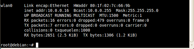
Getting WiFi Working on the A13-OLinuXino-MICRO
Tutorial
September 30, 2013
Configure an SD Card Image for Better Compression
Configure an SD Card Image for Better Compression
Tutorial
September 28, 2013
How To Backup an SD Card Image
How To Backup an SD Card Image
Tutorial
September 28, 2013
Getting Started with the Olimex A13-OLinuXino-MICRO
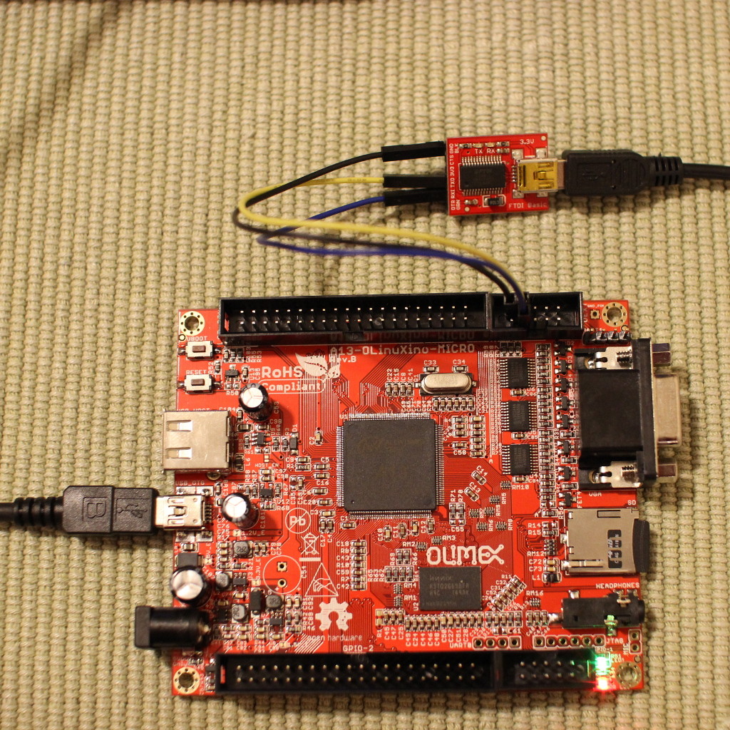
Getting Started with the Olimex A13-OLinuXino-MICRO
Tutorial
September 28, 2013