This tutorial covers the basics of using I2C with ESP-IDF and demonstrates how to read temperature from a simple temperature sensor (TI TMP102). You can watch a video version of this guide here:
What is I2C?
Inter-Integrated Circuit (I2C) is a synchronous, multi-master, multi-slave serial communication protocol developed by Philips Semiconductors in the early 1980s. Despite its relatively low transmission speeds compared to modern protocols, I2C remains incredibly popular for connecting microcontrollers to peripheral devices like sensors, displays, and memory chips.
I2C uses only two wires for communication:
- SDA (Serial Data): Carries the actual data being transmitted
- SCL (Serial Clock): Provides the clock signal that synchronizes data transmission
The protocol operates on a master-slave architecture where one device (the master/controller) initiates communication and controls the clock line, while other devices (slaves/targets) respond when addressed. Multiple devices can share the same I2C bus, with each slave having a unique 7-bit address.
Key characteristics of I2C include:
- Open-drain outputs requiring pull-up resistors
- Start and stop conditions to frame communications
- Acknowledgment bits to confirm successful data reception
- Support for different speed modes (Standard: 100 kHz, Fast: 400 kHz, High-speed: up to 3.4 MHz)
SparkFun has a great introduction to I2C tutorial, if you would like to dive into the technical details of the protocol.
Hardware Connections
If you would like to use real hardware for this guide, you will need:
- ESP32-S3-DevKitC (you can also use a Seeed Studio XIAO ESP32S3)
- TMP102 temperature sensor breakout board
- Header pins
- Breadboard
- Jumper wires
Connect the ESP32 development board to the TMP102 breakout board as follows:
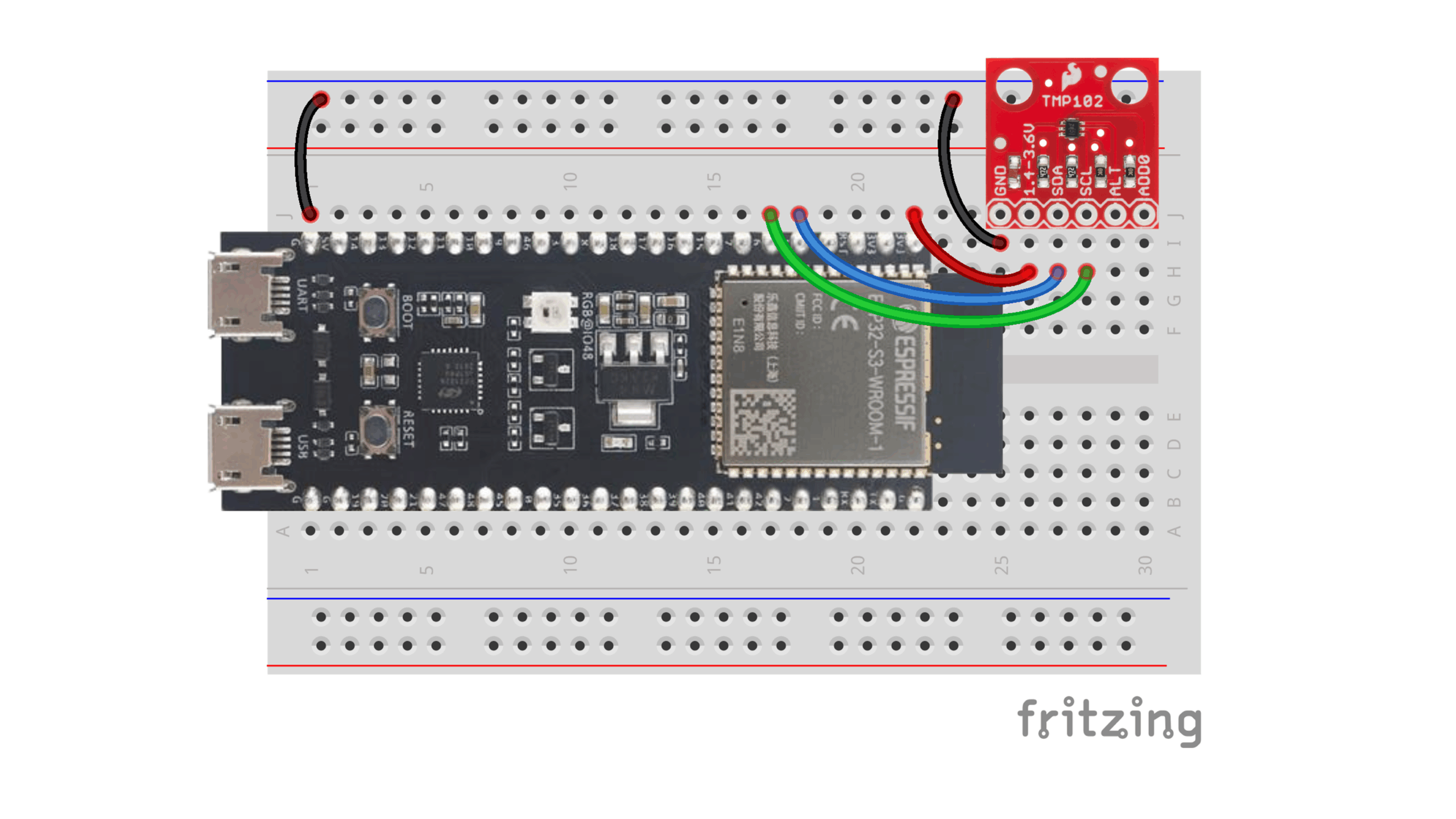
Note that I’ll also demonstrate how to use QEMU to emulate the ESP32 and TMP105 later in the tutorial (if you prefer to avoid using real hardware).
Reading Temperature from the TMP102
The TMP102 is a digital temperature sensor that communicates via I2C and provides temperature readings with 12-bit resolution (0.0625°C per bit). Understanding how to read from its temperature register requires examining the sensor’s internal structure and communication protocol, which we can obtain from the TMP102 datasheet.
TMP102 I2C Address and Registers
The TMP102 has a default I2C address of 0x48 when the ADD0 pin is connected to ground (which is the default for the SparkFun breakout board). The sensor contains four main registers:
- Temperature Register (0x00): Contains the current temperature reading (read-only)
- Configuration Register (0x01): Controls sensor operation modes
- T_LOW Register (0x02): Sets lower temperature threshold
- T_HIGH Register (0x03): Sets upper temperature threshold
Temperature Data Format
The temperature register stores data in a 12-bit format across two bytes:
- Byte 1 (MSB): Contains temperature bits T11 through T4
- Byte 2 (LSB): Contains temperature bits T3 through T0 in the upper 4 bits, with the lower 4 bits always zero
To convert the raw temperature data to degrees Celsius:
- Combine the two bytes:
temperature = (byte1 << 8) | byte2 - Right-shift by 4 bits to align the 12-bit value:
temperature >>= 4 - Multiply by the resolution:
temperature_celsius = temperature * 0.0625
For negative temperatures, the sensor uses two’s complement format, so the same conversion process applies automatically when using signed integer variables.
Making I2C Calls in ESP-IDF
ESP-IDF provides a comprehensive I2C master driver API that simplifies communication with I2C devices. The typical workflow involves three main steps:
- Configure the I2C bus with i2c_new_master_bus()
- Configure the device on the bus with i2c_master_bus_add_device()
- Use i2c_master_transmit_receive() for the common pattern of writing a register address and then reading data from that register
Create Demo Project
For this tutorial, I’ll assume you already have the ESP-IDF toolchain installed and working (if not, check out my Getting Started with ESP-IDF post first). Create a new project with the following structure:
/workspace/apps/i2c_temperature_demo/
├── CMakeLists.txt
└── main/
    ├── CMakeLists.txt
    └── main.c
In the top-level CMakeLists.txt, enter the following:
# Required CMake version
cmake_minimum_required(VERSION 3.16)

# Set up ESP-IDF build environment
include($ENV{IDF_PATH}/tools/cmake/project.cmake)

# Project name
project(app)
In main/CMakeLists.txt, enter the following:
idf_component_register(
    SRCS "main.c"
    INCLUDE_DIRS ""
)
In main/main.c, enter the following:
#include <stdio.h>
#include "driver/i2c_master.h"
#include "freertos/FreeRTOS.h"
// Settings
static const i2c_port_num_t i2c_port = 0; // -1 for auto-select
static const gpio_num_t i2c_sda_pin = 5; // GPIO number for SDA
static const gpio_num_t i2c_scl_pin = 6; // GPIO number for SCL
static const uint8_t i2c_glitch_ignore_cnt = 7; // 7 is typical
static const uint16_t tmp10x_addr = 0x48; // TMP102/105 I2C address
static const uint32_t tmp10x_scl_speed_hz = 100000; // 100kHz (standard mode)
static const uint32_t sleep_time_ms = 1000;
// Constants
static const uint8_t tmp10x_reg_temp = 0x00;
void app_main(void)
{
esp_err_t esp_ret;
i2c_master_bus_handle_t i2c_bus;
i2c_master_dev_handle_t tmp10x_dev;
uint8_t reg;
uint8_t data[2];
int16_t temperature;
// Set I2C bus configuration
i2c_master_bus_config_t bus_config = {
.i2c_port = i2c_port,
.sda_io_num = i2c_sda_pin,
.scl_io_num = i2c_scl_pin,
.clk_source = I2C_CLK_SRC_DEFAULT,
.glitch_ignore_cnt = i2c_glitch_ignore_cnt,
.flags.enable_internal_pullup = true,
};
// Initialize the I2C bus
esp_ret = i2c_new_master_bus(&bus_config, &i2c_bus);
if (esp_ret != ESP_OK) {
printf("Error: Failed to initialize I2C bus\r\n");
abort();
}
// Set I2C device configuration
i2c_device_config_t dev_config = {
.dev_addr_length = I2C_ADDR_BIT_LEN_7,
.device_address = tmp10x_addr,
.scl_speed_hz = tmp10x_scl_speed_hz,
};
// Initialize the TMP10x I2C device on the bus
esp_ret = i2c_master_bus_add_device(i2c_bus, &dev_config, &tmp10x_dev);
if (esp_ret != ESP_OK) {
printf("Error: Failed to initialize I2C device\r\n");
abort();
}
// Superloop
while (1) {
// Delay
vTaskDelay(sleep_time_ms / portTICK_PERIOD_MS);
// Store register address in buffer
reg = tmp10x_reg_temp;
// Read temperature
esp_ret = i2c_master_transmit_receive(tmp10x_dev, ®, 1, data, 2, -1);
if (esp_ret != ESP_OK) {
printf("Error: Failed to read temperature\r\n");
continue;
}
// Convert data to temperature (deg C)
temperature = (data[0] << 8) | data[1];
temperature >>= 4;
temperature *= 0.0625;
// Print temperature
printf("Temperature: %d deg C\r\n", temperature);
}
}
Understanding the Code
Let’s examine the key sections of the provided main.c file:
Global Configuration Variables
static const i2c_port_num_t i2c_port = 0;
static const gpio_num_t i2c_sda_pin = 5;
static const gpio_num_t i2c_scl_pin = 6;
static const uint8_t i2c_glitch_ignore_cnt = 7;
static const uint16_t tmp10x_addr = 0x48;
static const uint32_t tmp10x_scl_speed_hz = 100000;
These constants define the hardware configuration: which I2C port to use, which GPIO pins for SDA and SCL, the sensor’s I2C address, and the communication speed (100 kHz for standard mode).
Bus and Device Setup
The code initializes the I2C bus with pull-up resistors enabled and a glitch filter count of 7. The i2c_glitch_ignore_cnt sets the number of clock cycles that the I2C controller should ignore I2C noise for. In other words, the I2C controller will only consider signal changes that persist for more than 7 clock cycles as valid. The device is then added to the bus with the TMP102’s address and communication speed.
Main Reading Loop
The core functionality occurs in an infinite loop:
while (1) {
vTaskDelay(sleep_time_ms / portTICK_PERIOD_MS);
reg = tmp10x_reg_temp;
esp_ret = i2c_master_transmit_receive(tmp10x_dev, ®, 1, data, 2, -1);
if (esp_ret != ESP_OK) {
printf("Error: Failed to read temperature\r\n");
continue;
}
temperature = (data[0] << 8) | data[1];
temperature >>= 4;
temperature *= 0.0625;
printf("Temperature: %d deg C\r\n", temperature);
}This loop:
- Waits for the specified delay period
- Writes the temperature register address (0x00) to the sensor
- Reads two bytes of temperature data
- Converts the raw data to degrees Celsius
- Prints the result
Note that the code uses integer arithmetic for simplicity, truncating decimal portions of the temperature reading.
Error Handling
The code implements proper error checking after each ESP-IDF function call. For bus and device initialization, errors cause the program to abort. During temperature reading, errors are logged but the program continues, attempting to read again after the next delay period.
Building and Flashing the Program
To build and flash this I2C temperature monitoring program:
1. Set Up the Build Environment
Navigate to your project directory and configure the target ESP32 variant:
cd /path/to/your/project
idf.py set-target esp32s3  # or esp32, esp32c3, etc.
2. Build the Project
Compile the project and generate the binary files:
idf.py buildThis creates the necessary binary files in the build directory, including the bootloader, partition table, and application binary.
3. Flash to Hardware
Connect your ESP32 device and flash the program:
python -m esptool.py --port "<SERIAL_PORT>" --chip auto --baud 921600 \
    --before default_reset --after hard_reset write_flash \
    --flash_mode dio --flash_freq 40m --flash_size auto \
    0x0 build/bootloader/bootloader.bin \
    0x8000 build/partition_table/partition-table.bin \
    0x10000 build/your_app_name.bin
Replace <SERIAL_PORT> with your actual serial port and adjust the binary paths as needed.
4. Monitor Serial Output
Open a serial monitor to view the temperature readings:
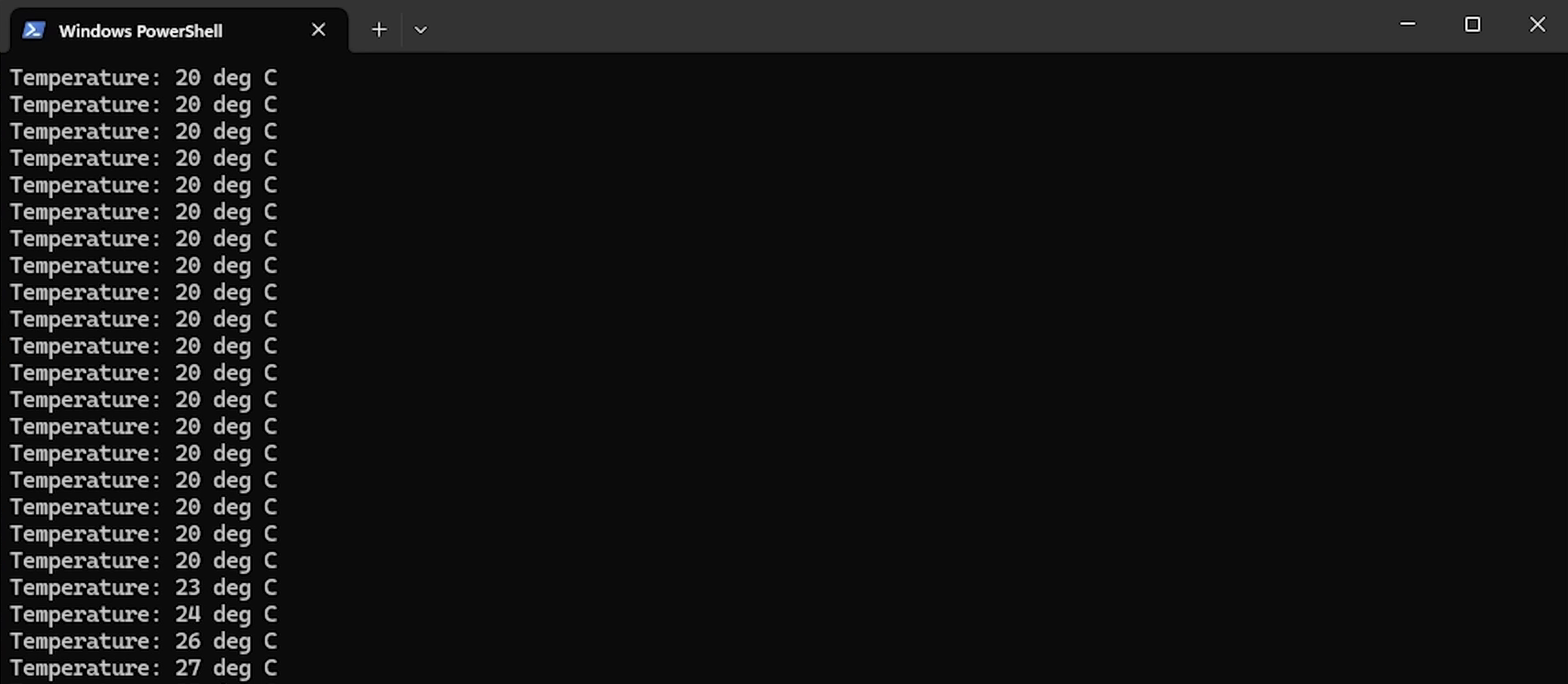
python -m serial.tools.miniterm "<SERIAL_PORT>" 115200You should see the temperature value being printed to the console. Feel free to lightly touch or breath on your TMP102 sensor to watch the temperature rise.
Running with QEMU Emulation
ESP-IDF supports QEMU emulation for testing I2C code without physical hardware. The emulated environment includes a virtual TMP105 sensor (very similar to the TMP102) that responds to the same I2C commands.
Build for QEMU
Set the target back to the standard ESP32 (QEMU works best with this variant in my experience):
idf.py set-target esp32
idf.py build
Launch QEMU
Start the emulated ESP32 with the I2C temperature sensor:
idf.py qemuThis command compiles the project if needed and launches QEMU with the appropriate virtual hardware configuration.
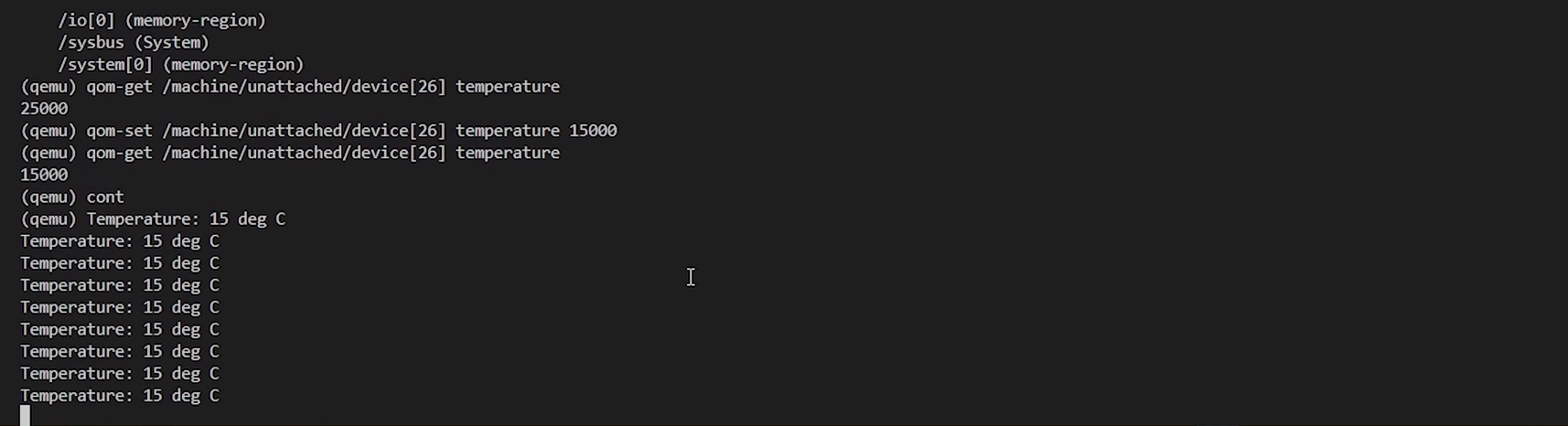
Interact with the Emulated Sensor
Once QEMU is running, you can access the QEMU monitor console by pressing Ctrl+A followed by C. This allows you to interact with the virtual TMP105 sensor. For example, we can adjust the temperature (in thousandths of a degree Celsius):
(qemu) stop
(qemu) qom-get /machine/unattached/device[26] temperature
(qemu) qom-set /machine/unattached/device[26] temperature 15000
(qemu) cont
These commands stop the emulation, check the current virtual temperature (25°C = 25,000 millidegrees), set it to 15°C, and resume execution. The running ESP32 program will detect and display the new temperature value.
To exit the emulator, return to the monitor console (Ctrl+A, C) and type:
(qemu) quitGoing Further
We covered how to interface with temperature sensors using ESP-IDF’s I2C master driver. The same principles apply to other I2C devices: configure the bus, register the device, and use the transmit/receive functions to communicate. I recommend checking out the various I2C examples in ESP-IDF if you’d like to see how to use other I2C functionality.
If you would like to go further, check out my IoT Firmware Development with ESP32 and ESP-IDF course. In the course, we cover the basics of ESP-IDF, reading from sensors, connecting to the internet via WiFi, posting data via HTTP REST calls, securing connections with TLS, and interacting with MQTT brokers.
