This tutorial will walk you through the process of setting up ESP-IDF using a Docker container and build a basic blinking LED example from this repository: https://github.com/ShawnHymel/course-iot-with-esp-idf/.
Here is a video version of the guide:
Table of Contents
Why ESP-IDF?
The Espressif IoT Development Framework (ESP-IDF) is the official software development kit for the ESP32 family of microcontrollers. Built on a fork of FreeRTOS, it allows developers to create sophisticated, multi-threaded embedded applications that can handle the demands of real-world IoT systems. ESP-IDF includes a comprehensive set of libraries for controlling GPIO pins, interfacing with sensors, and implementing full networking stacks for Wi-Fi, Bluetooth, and Ethernet. It is designed to provide the flexibility, performance, and reliability needed for professional IoT firmware development, making it the preferred choice for engineers building connected products at scale.
While Arduino remains popular for hobbyist projects, there are many situations where ESP-IDF is the better choice. Developers who need production-ready code, precise control over system resources, and access to advanced configuration tools will find ESP-IDF indispensable. Its integration with FreeRTOS enables multi-tasking, while its modular architecture and rich peripheral support make it well-suited for applications that require scalability, security, and long-term maintainability. If your goal is to move beyond quick prototypes and into the realm of robust, deployable IoT devices, learning ESP-IDF is an essential step.

Hardware Setup
You technically do not need any hardware for this tutorial if you wish to emulate your program in qemu. However, if you wish to try it with real hardware, you will need an ESP32 development board, an LED, a 220 Ω resistor, a breadboard, and some jumper wires. Here is a list of the recommended parts:
- One of the following ESP32 development boards*
- SparkFun TMP102 Temperature Sensor Breakout Board
- LED
- 220 Ω resistor
- Jumper wires (M/M)
- Solderless breadboard
- USB cable for your development board
* Any ESP32 (Xtensa core) development board should work for this tutorial (in theory), but you may need to change pins in code or bootloader address when flashing.
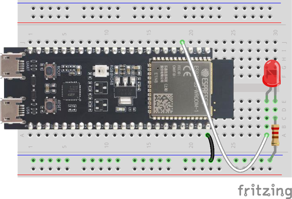
Connect an LED (through the 220 Ω resistor) to GPIO 4 on your ESP32 dev board. This is pin 4 on the ESP32-S3-DevKitC:
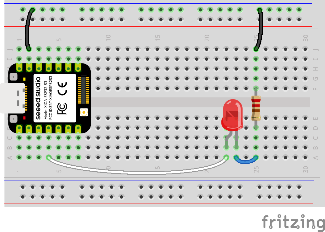
Or if you are using the XIAO ESP32S3, connect the LED to pin D3:
Install ESP-IDF
All code for this tutorial, future ESP32 tutorials in this series, and in the related IoT Firmware Development with ESP32 and ESP-IDF course are built using a pre-configured Docker image. By doing this, software versions (e.g. ESP-IDF) can be pinned and the environment can be set to work across all major operating systems, giving users a seamless, unified experience.
You can also follow the official instructions to install ESP-IDF locally on your computer. Just note that future directions and screenshots in this tutorial will assume you are using VS Code connected to a Docker container pre-configured with ESP-IDF.
Required Dependencies
Install the following programs on your computer:
- (Windows) WSL 2
- Docker Desktop
- Python
Windows users will likely need to install the virtual COM port (VCP) drivers from SiLabs.
Download the following repository somewhere on your computer: https://github.com/ShawnHymel/course-iot-with-esp-idf/ (using either git or click Code > Download ZIP).
Open a terminal, navigate to the repository directory, and install the following dependencies:
Linux/macOS:
cd course-iot-with-esp-idf/
python -m venv venv
source venv/bin/activate
python -m pip install pyserial==3.5 esptool==4.8.1
Windows (PowerShell):
cd course-iot-with-esp-idf/
Set-ExecutionPolicy -Scope CurrentUser -ExecutionPolicy Unrestricted -Force
python -m venv venv
venv\Scripts\activate
python -m pip install pyserial==3.5 esptool==4.8.1
Build Docker Image
From the repository’s directory, build the image (this will take some time). Note that we pass in the computer’s hostname so it can be added as a Subject Alternative Name (SAN) in the OpenSSL configuration. This allows TLS connections to use mDNS to connect to the host and verify the Common Name (or SAN) using <MY_HOSTNAME>.local in addition to localhost (if you would like to use TLS with the MQTT broker in the image, which is covered in the course):
docker build -t env-esp-idf -f Dockerfile.esp-idf --build-arg HOSTNAME=$(hostname) .Note that this will take some time as it downloads and installs Debian and the required ESP-IDF tools. Feel free to look at the Dockerfile to see what’s being installed in the image.
Run Docker Image
Run the Docker image (Linux, macOS, Windows/PowerShell):
docker run --rm -it -p 1883:1883 -p 8080:8080 -p 8081:8081 -p 8800:8800 -p 8883:8883 -p 22001:22 -v "$(pwd)/workspace:/workspace" -w /workspace env-esp-idfImportant! If asked for your username and password while in the container, know that these are the defaults (feel free to change them in the Dockerfile and rebuild):
- Username: root
- Password: espidf
You have a few options to connect to the development environment:
Option 1: Connect via Browser
If you do not want to install VS Code locally, you can simply open a browser and navigate to http://localhost:8800/. The Docker image runs an instance of VS Code Server, which allows you to run VS Code inside a browser.
Option 2: VS Code with Dev Containers
Dev Containers is a wonderful extension for letting you connect your local VS Code to a Docker container. In your local VS Code, install the Dev Containers extension.
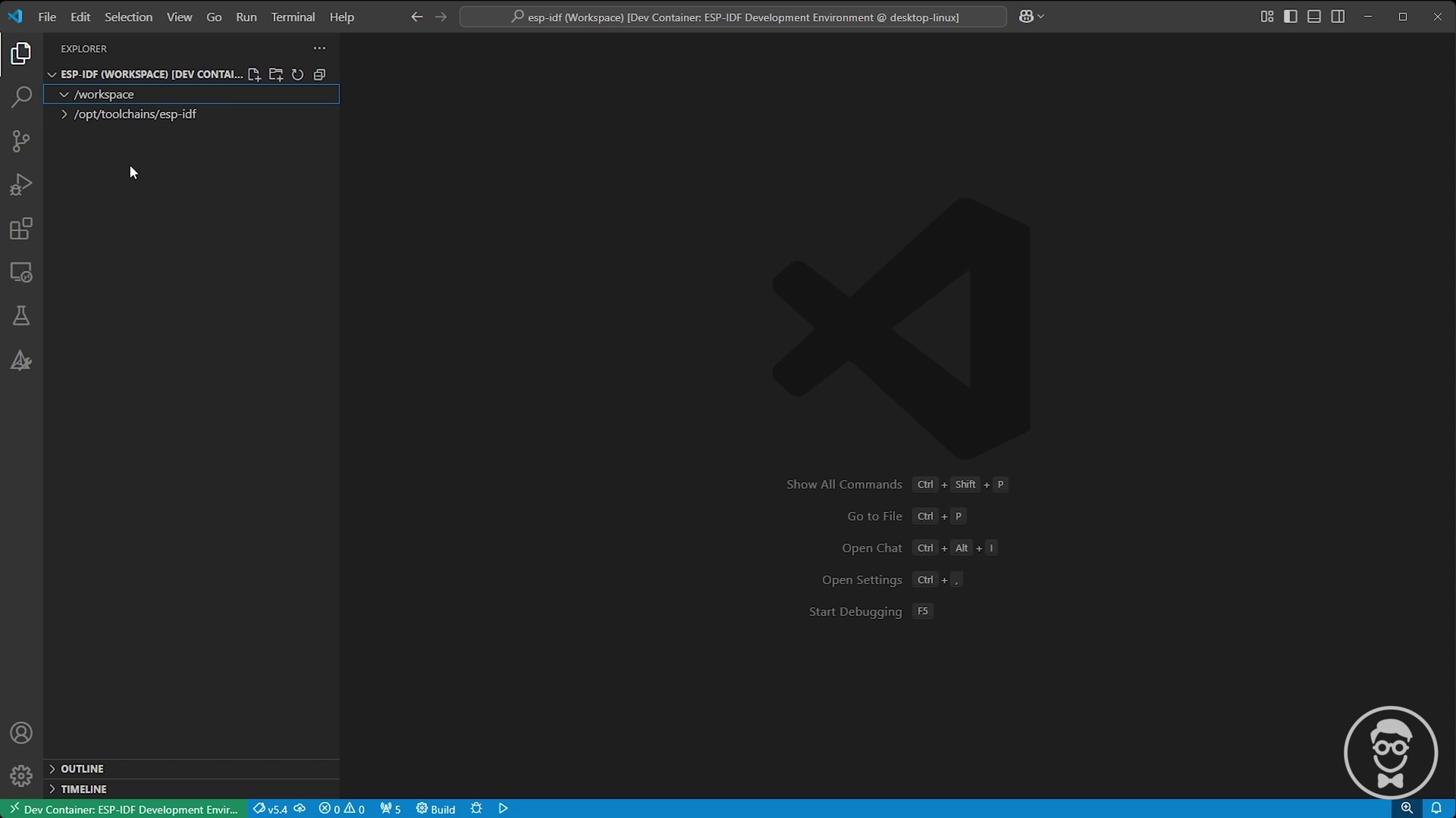
Open the command palette (Ctrl+Shift+P) and search for Dev Containers: Attach to Running Container. Click it, and you should see a container of your env-esp-idf image running. Click the container from the list. A new VS Code window will open and install the required dependencies.
Go to File > Open Workspace from File… and select the /esp-idf.code-workspace file when prompted. Enter the password (mosquitto) again if requested. This should configure your VS Code workspace with the /workspace directory mapped from the host directory alongside the required toolchain directories (e.g. /opt/toolchains/esp-idf).
Recommended Extensions
I recommend installing the following VS Code extensions to make working with ESP-IDF easier (e.g. IntelliSense). Note that the .code-workspace file will automatically recommend them.
At this point, you should have your development environment configured and ready for creating ESP-IDF applications!
Create Blink Application
Let’s write our first blink application using ESP-IDF! Note that /workspace/apps already contains a number of demo applications from the course. Feel free to look through those. We’ll be recreating the /workspace/apps/blinky project from scratch so you can see how to make your own ESP-IDF projects.
Project Structure
Create a folder named my-blink in /workspace/apps, and in there, create a set of files and folders as follows:
/workspace/apps/my-blink/
├── CMakeLists.txt
├── main
    ├── CMakeLists.txt
    └── main.c
my-blink/CMakeLists.txt
This is the top-level project CMakeLists.txt that tells CMake where to find the necessary ESP-IDF extensions and gives the project a name (called app). Fill out the file with the following:
# Required CMake version
cmake_minimum_required(VERSION 3.16)

# Set up ESP-IDF build environment
include($ENV{IDF_PATH}/tools/cmake/project.cmake)

# Project name
project(app)
my-blink/main/CMakeLists.txt
This is the directory-level CMakeLists.txt that tells CMake where to find the header and source files for this particular ESP-IDF component. Note that idf_component_register() is a special ESP-IDF function that registers a component (chunk of code, library, or executable) to the ESP-IDF build system.
idf_component_register(
    SRCS "main.c"
    INCLUDE_DIRS ""
)
my-blink/main/main.c
Here is our main application code:
#include <stdio.h>

#include "driver/gpio.h"
#include "freertos/FreeRTOS.h"

// Settings
static const gpio_num_t led_pin = GPIO_NUM_4;
static const uint32_t sleep_time_ms = 1000;

void app_main(void)
{
    uint8_t led_state = 0;

    // Configure the GPIO
    gpio_reset_pin(led_pin);
    gpio_set_direction(led_pin, GPIO_MODE_OUTPUT);

    // Superloop
    while (1) {

        // Toggle the LED
        led_state = !led_state;
        gpio_set_level(led_pin, led_state);

        // Print LED state
        printf("LED state: %d\n", led_state);

        // Delay
        vTaskDelay(sleep_time_ms / portTICK_PERIOD_MS);
    }
}
Note that we configure the GPIO as output with gpio_reset_pin() and gpio_set_direction(). We then use gpio_set_level() to toggle the pin on or off. You can read more about the available GPIO functions in ESP-IDF here.
ESP-IDF uses the familiar C printf() to print strings out of whichever serial console we have configured (USB by default). You can read about how ESP-IDF handles standard input/output functions here.
Finally, ESP-IDF is built on top of a forked version of FreeRTOS. That means most of the standard FreeRTOS functions are available within ESP-IDF (with some exceptions or modifications). vTaskDelay() is a common FreeRTOS function that’s used to sleep a thread (task) for a given number of ticks. The tick rate is set to 10 ms per tick (100 Hz) by default in ESP-IDF (you can change this value using Kconfig). FreeRTOS gives us the constant portTICK_PERIOD_MS, which tells us the number of milliseconds in a tick. So, we just divide our desired delay time by this constant to get the number of ticks we should pass to vTaskDelay(). Note that the resulting value will be truncated to the nearest number of whole ticks–keep that in mind when you are basing delays, waits, etc. on the system tick clock.
Build the Application
Save all your work. Now, let’s use ESP-IDF to build this application. Open a terminal (View > Terminal). We first need to set our desired target:
cd /workspace/apps/my-blink
idf.py set-target esp32s3
Then, build your project:
idf.py buildNote that because we mounted the workspace/ directory in the course repository directory to the container (with the -v option), we have access to anything in workspace/ on our host computer! That means you can save your work and flash the built binary manually.
Flash the Application
One of the downsides of working in a container is the limited options of passing a USB connection through the host machine to the container. That means the easy idf.py flash command will not work in most containers. To get around this, we’ll use the esptool that we installed on our host machine to flash the binary directly.
Plug your development board into your computer. If you are using the official Espressif DevKitC, you should connect the USB cable to the UART port (not the USB port). Figure out which serial port is assigned to your kit:
- Linux: something like /dev/ttyUSB0 or /dev/ttyACM0
- macOS: something like /dev/tty.usbmodem144101
- Windows: use the Device Manager to identify the port, something like COM6
In a terminal on your host computer (not in the container!), navigate to the repository directory and activate the Python virtual environment (if you have not already done so):
Linux/macOS:
cd course-iot-with-esp-idf/
source venv/bin/activate
Windows (PowerShell):
cd course-iot-with-esp-idf/
venv\Scripts\activate
From there, navigate to the my-blink/ directory and flash the binary (replace <SERIAL_PORT> with the location or COM of your serial port).
Important! If you are using a non-S3 variant, the memory address of the bootloader might be different! While the ESP32-S3 bootloader needs to be at address 0x0, other variants (like the base ESP32) might be at 0x1000. See the official documentation for your particular variant.
cd workspace/apps/my-blink/
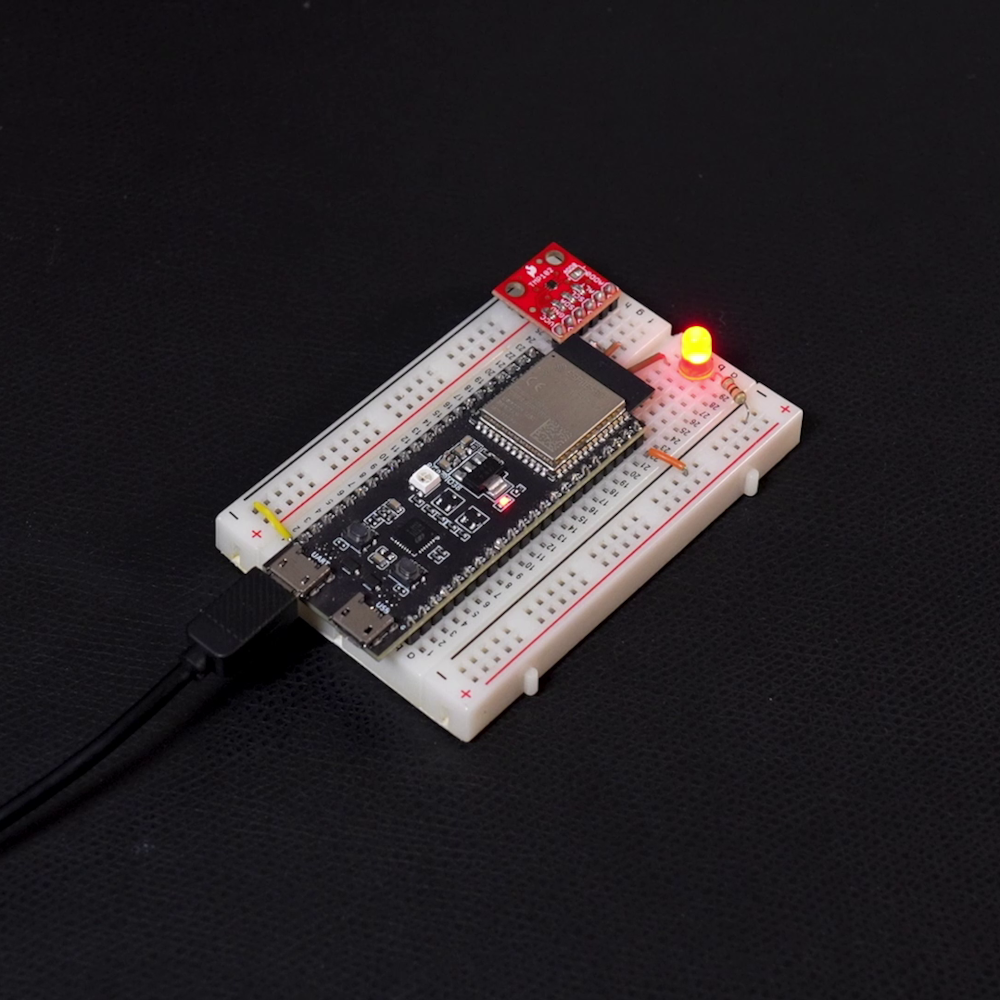
python -m esptool --port "<SERIAL_PORT>" --chip auto --baud 921600 --before default_reset --after hard_reset write_flash --flash_mode dio --flash_freq 40m --flash_size detect 0x0 .\build\bootloader\bootloader.bin 0x8000 .\build\partition_table\partition-table.bin 0x10000 .\build\app.binWith any luck, you should see the LED on your board flashing!
You can also use your favorite serial terminal to connect to the ESP32 to see our println() strings. To unify the experience, I also had you install the pyserial package earlier, which you can use as a barebones serial terminal in Python:
python -m serial.tools.miniterm "<SERIAL_PORT>" 115200That should give you the boot messages along with the state of your LED:
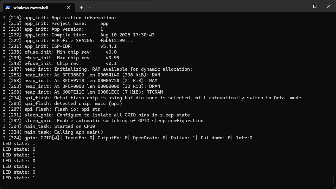
Press ctrl+] to exit.
Emulating with QEMU
So, you don’t have the hardware? Or you just want to try ESP-IDF without committing to buying something? Great! You can actually emulate your program in Espressif’s forked version of QEMU.
While QEMU lacks a lot of hardware accessories (e.g. sensors, motors) and underlying physical layers (e.g. WiFi), you can still do a lot with it! It also opens up the possibility of creating automated tests as part of a CI/CD pipeline.
ESP-IDF comes with this version of QEMU already installed. The bad news is that (as of ESP-IDF v5.4), the ESP32-S3 variant had some bugs in QEMU. So, I recommend changing your target to the base ESP32.
Back in the development container, run the following. Note that the idf.py qemu command will automatically build your project and run it in QEMU.
cd /workspace/apps/my-blink
idf.py set-target esp32
idf.py qemu monitor
This should build and run your application in QEMU.
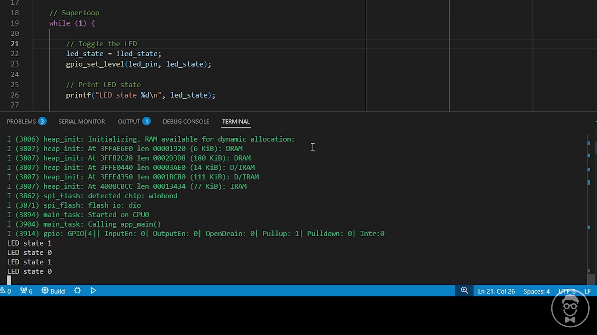
Note that the monitor subcommand tells ESP-IDF to run QEMU in “monitor” mode, which nicely colors the output and allows you to enter commands into the serial input (similar to using a serial terminal like miniterm). Exit with ctrl+].
If you omit monitor (i.e. idf.py qemu), then you run the application in base QEMU mode. There is no color coding, and you can interact with QEMU directly: press ctrl+a, c to get an interactive terminal where you can enter QEMU commands. Exit with ctrl+a, x.
Conclusion
Hopefully, this helps you get a start using ESP-IDF! It is a flexible and powerful framework for writing lower-level applications for various ESP32 targets (as opposed to more portable applications in e.g. Arduino).
If you would like to dig deeper, consider taking my IoT Firmware Development with ESP32 and ESP-IDF course, where we cover the basics of ESP-IDF, reading from sensors, connecting to the internet via WiFi, posting data via HTTP REST calls, securing connections with TLS, and interacting with MQTT brokers.

Thanks for the wonderful tutorial. I’m having trouble when i return to the project after closing everything, and come back the next day.
(Windows) – When I ‘cd’ into the course-iot-with-esp-idf/ directory
Then try to run the docker container I get the error:
”
failed to connect to the docker API at npipe:////./pipe/dockerDesktopLinuxEngine; check if the path is correct and if the daemon is running: open //./pipe/dockerDesktopLinuxEngine: The system cannot find the file specified.
”
Docker build throws the same error. This is with the venv activated in win PS.
NB: Was able to run through the entre tutorial with no issue the previous day. Is there a way to pick back up if you stop halfway through?
Thanks
MD
Hey there, problem solved. Just had to open up docker desktop, thanks MD
Good to know you got it figured out, and I appreciate letting others know what the solution is!