As a third step to learning the Teensy LC, I decided to tackle input capture. I discovered that there is no separate interrupt vector for input capture; it is the same vector used by the timer interrupt. This means that if we are looking for a timer overflow event as well as a pin change for input capture, we must check for that specific interrupt flag within the interrupt service routine (ISR).
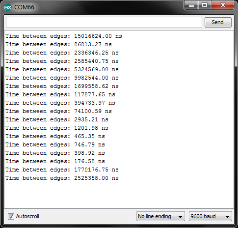
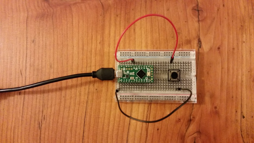
To try the example, connect a button to pin 20 of the Teensy LC, and connect the other side of the button to the Teensy LC’s ground (G) pin. Run the code and open a serial terminal. Whenever you press the button, you will see the time (in nanoseconds) between edges. Push the button a number of times, and you’ll see examples of switch bounce.
/**
 * Teensy_LC_IC_Test.ino
 * Shawn Hymel
 * May 21, 2015
 *
 * Set up an interrupt service routine and input capture to
 * display the time between edges of a button push. It will show
 * button bounce!
 *
 * Pin 20 on the Teensy LC is PORT D, pin 5. It is pin 46 on the
 * 48-pin QFN. This is tied to TPM0_CH5 with pin function ALT4.
 *
 * Connect: Teensy LC pin 16 -> Button -> Teensy LC GND
 *
 * Teensy LC schematic: https://www.pjrc.com/teensy/schematic.html
 * MKL26Z64 datasheet: https://www.pjrc.com/teensy/KL26P121M48SF4RM.pdf
 */

volatile uint32_t count = 0;
volatile uint32_t prev_val = 0;
volatile uint32_t ovf_count = 0;
volatile uint8_t ic_flag = 0;
float gap;

void setup() {

  // Set up our Serial port
  Serial.begin(9600);

  // The order of setting the TPMx_SC, TPMx_CNT, and TPMx_MOD
  // seems to matter. You must clear _SC, set _CNT to 0, set _MOD
  // to the desired value, then you can set the bit fields in _SC.

  // Clear TPM0_SC register (p. 572)
  FTM0_SC = 0;

  // Reset the TPM0_CNT counter (p. 574)
  FTM0_CNT = 0;

  // Set overflow value (modulo) (p. 574)
  FTM0_MOD = 0xFFFF;

  // Set TPM0_SC register (p. 572)
  // Bits | Va1ue | Description
  //  8   |    0  | DMA: Disable DMA
  //  7   |    1  | TOF: Clear Timer Overflow Flag
  //  6   |    1  | TOIE: Enable Timer Overflow Interrupt
  //  5   |    0  | CPWMS: TPM in up counting mode
  // 4-3  |   01  | CMOD: Counter incrememnts every TPM clock
  // 2-0  |  000  | PS: Prescale = 1
  FTM0_SC = 0b011001000;

  // Set TPM0_C5SC register (Teensy LC - pin 20) (p. 575)
  // As per the note on p. 575, we must disable the channel
  // first before switching channel modes. We also introduce
  // a magical 1 us delay to allow the new value to take.
  // Bits | Va1ue | Description
  //  7   |    0  | CHF: Do nothing
  //  6   |    1  | CHIE: Enable Channel Interrupt
  // 5-4  |   00  | MS: Input capture
  // 3-2  |   11  | ELS: Capture on rising and falling edge
  //  1   |    0  | Reserved
  //  0   |    0  | DMA: Disable DMA
  FTM0_C5SC = 0;
  delayMicroseconds(1);
  FTM0_C5SC = 0b01001100;

  // Set PORTD_PCR5 register (Teensy LC - pin 20) (p. 199)
  // Bits | Value | Description
  // 10-8 |   100 | MUX: Alt 4 attach to TPM0_CH5 (p. 179)
  //  7   |     0 | Reserved
  //  6   |     0 | DSE: Low drive strength
  //  5   |     0 | Reserved
  //  4   |     0 | PFE: Disable input filter
  //  3   |     0 | Reserved
  //  2   |     0 | SRE: Fast slew rate if output
  //  1   |     1 | PE: Enable pull-up/down
  //  0   |     1 | PS: Internal pull-up
  PORTD_PCR5 = 0b10000000011;

  // Nested Vector Interrupt Controller (NVIC) (p. 57)
  // Also: Chapter 4.2 of the Generic User Guide
  // Our FTM0 interrupt number is 17 (as per kinetis.h). We can
  // use that to set up our interrupt vector and priority.

  // Set the urgency of the interrupt. Lower numbers mean higher
  // urgency (they will happen first). Acceptable values are
  // 0, 64, 128, and 192. Default is 128. We set the priority
  // (2nd byte) in the register for the FTM0 interrupt (&E000_E410)
  // to 64.
  NVIC_SET_PRIORITY(IRQ_FTM0, 64);

  // Enable the interrupt vector. In this case, we want to execute
  // the ISR (named "ftm0_isr()" for Teensy) every time TPM0
  // overflows. We set bit 17 of &E000_E100.
  NVIC_ENABLE_IRQ(IRQ_FTM0);
  // Same as: NVIC_ISER0 |= (1 << 17);
}

void loop() {

  // If an input capture event has occurred, print the time
  // between edges
  if ( ic_flag ) {

    // Time between edges
    // (1 / 48MHz) * (1 prescaler) = 20.83 ns per count
    gap = count * (1 / 48.0);
    Serial.print("Time between edges: ");
    Serial.print(gap);
    Serial.println(" ns");

    // Reset input capture flag
    ic_flag = 0;
  }
}

// "ftm0_isr" is an interrupt vector defined for the Teensy
void ftm0_isr(void) {

  uint32_t val;

  // If we got to this ISR via timer overflow, we want to clear
  // the timer overflow flag. We also want to count the number of
  // overflows that have occurred.
  if ( FTM0_SC & (1 << 7) ) {
    FTM0_SC |= (1 << 7);
    ovf_count++;
  }

  // If we got here from the input capture, we want to clear the
  // channel flag.
  if ( FTM0_C5SC & (1 << 7) ) {
    FTM0_C5SC |= (1 << 7);

    // We should only continue if we have handled the previous
    // input capture
    if ( !ic_flag ) {

      // Retrieve the counter value and compare it to the last one.
      // Take into account any overflows that have occured.
      val = FTM0_C5V;
      if ( ovf_count == 0 ) {
        count = val - prev_val;
      } else {
        count = (0x10000 - prev_val) + ((ovf_count - 1) << 16) + val;
      }

      // Save the counter value and reset the overflow counter
      prev_val = val;
      ovf_count = 0;

      // Set a flag so that we can read the count in the main loop
      ic_flag = 1;
    }
  }
}