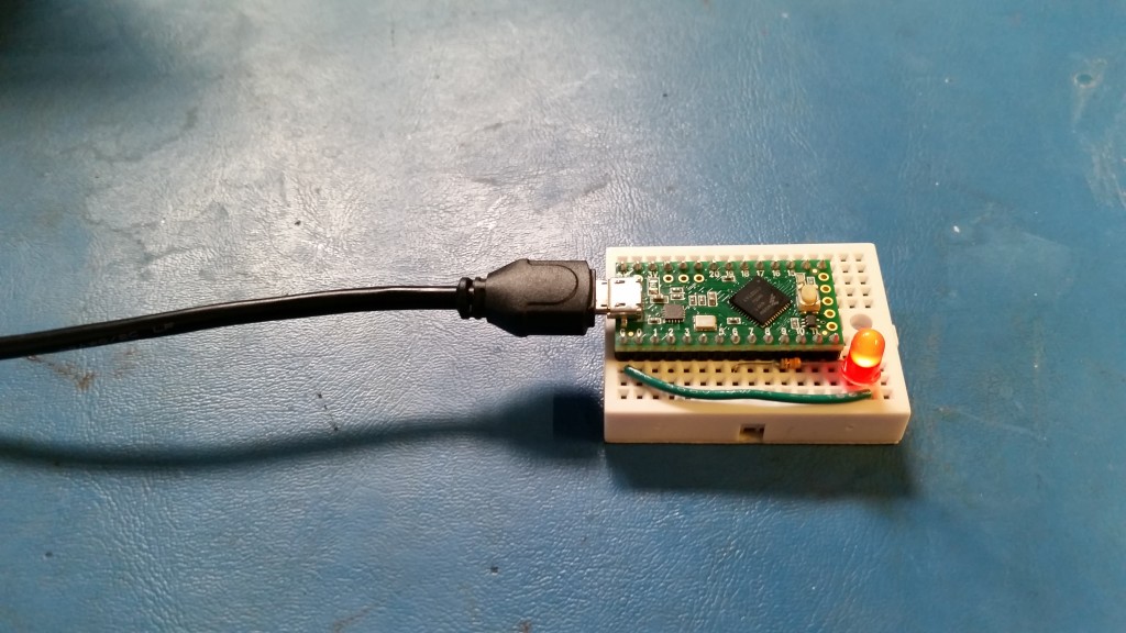
I’m in the process of learning how to use the Teensy LC, which is the newest Arduino-compatible module from PJRC. It is built around the MKL26Z64VFT4 (ARM Cortex-M0+), which can be had for around $2.20 for 100 (according to Digi-Key). I really like the microcontroller, as it is much more powerful than the ubiquitous ATmega 328p (not that I don’t like the 328p) for about the same price.
The awesome people at PJRC have gone through the process of creating a set of libraries and hardware definitions so that you can program the entire Teensy line from Arduino. It is quite slick, and if you have not tried it yet, I suggest you give it a shot. It does require installing some software on top of the Arduino IDE, but it opens up the world of ARM to Arduino users.
Because I have decided to use the Teensy LC (or, more specifically, the MKL26Z64VFT4) for a personal project, I wanted to learn how to manually set up interrupts. As it turns out, ARM interrupts are more complicated than the interrupts found in most ATmega processors. More importantly, I wanted to learn how to do this from the Arduino IDE (because reasons). PJRC still has many of the labels for registers and bit fields set to the Teensy 3.1, which work well enough for the Teensy LC, but might not be correct.
To get the example code to work, attach an LED (with a limiting resistor, of course) to pin 6 of the Teensy LC, and upload the code from the Teensyduino IDE. There is definitely a better way of doing this (using labels for bit fields instead of hardcoded values, for example), but this was a learning exercise on how to appropriately set the timer registers.
The program sets up a hardware PWM on pin 6 of the Teensy LC and then does nothing in the while loop. In essence, I’m doing analogWrite() the hard way.
[Edit 05/24/15] It looks like I was setting FTM0_C4SC incorrectly. As per the notes on p. 575 of the datasheet, you need to set it to 0 first (“channel must first be disabled”). We add a magical delay (1 microsecond) to allow the register to be set to 0 before writing the value. Additionally, the edge bits were wrong. They should have been 0b10 to have the PWM value set on timer reset and clear on value match. These changes have been reflected below.
/**
 * Teensy_LC_PWM_Test.ino
 * Shawn Hymel
 * May 6, 2015
 *
 * Manually set PWM on a Teensy LC on pin 6. Put an LED on pin
 * 6 and adjust the FTM0_CNT value (PWM value).
 *
 * Pin 6 on the Teensy LC is PORT D, pin 4. It is pin 45 on the
 * 48 pin QFN.
 *
 * Connect: Teensy LC pin 6 -> 220 Ohm -> red LED -> Teensy LC GND
 *
 * Teensy LC schematic: https://www.pjrc.com/teensy/schematic.html
 * MKL26Z64 datasheet: https://www.pjrc.com/teensy/KL26P121M48SF4RM.pdf
 */

void setup() {

  // The order of setting the TPMx_SC, TPMx_CNT, and TPMx_MOD
  // seems to matter. You must clear _SC, set _CNT to 0, set _MOD
  // to the desired value, then you can set the bit fields in _SC.

  // Clear TPM0_SC register (p. 572)
  FTM0_SC = 0;

  // Reset the TPM0_CNT counter (p. 574)
  FTM0_CNT = 0;

  // Set overflow value (modulo) (p.574)
  FTM0_MOD = 0xFFFF;

  // Set TPM0_SC register (p. 572)
  // Bits | Va1ue | Description
  //  8   |    0  | DMA: Disable DMA
  //  7   |    1  | TOF: Clear Timer Overflow Flag
  //  6   |    1  | TOIE: Enable Timer Overflow Interrupt
  //  5   |    0  | CPWMS: TPM in up counting mode
  // 4-3  |   01  | CMOD: Counter incrememnts every TPM clock
  // 2-0  |  100  | PS: Prescale = 16
  FTM0_SC = 0b011001100;

  // Set TPM0_C4SC register (Teensy LC - pin 6) (p. 575)
  // As per the note on p. 575, we must disable the channel
  // first before switching channel modes. We also introduce
  // a magical 1 us delay to allow the new value to take.
  // Bits | Va1ue | Description
  //  7   |    1  | CHF: Clear Channel Flag
  //  6   |    1  | CHIE: Enable Channel Interrupt
  // 5-4  |   10  | MS: Edge-aligned PWM
  // 3-2  |   10  | ELS: Set on reload, clear on match
  //  1   |    0  | Reserved
  //  0   |    0  | DMA: Disable DMA
  FTM0_C4SC = 0;
  delayMicroseconds(1);
  FTM0_C4SC = 0b11101000;

  // Set PWM value (0 - 65535) to TPM0_C4V (p. 577)
  // This will produce a 5 ms pulse every 21.845 ms:
  // (1 / 48 MHz) * (16 prescaler) * (15000 count) = 5 ms
  // (1 / 48 MHz) * (16 prescaler) * (65535 count) = 21.845 ms
  FTM0_C4V = 15000;

  // Set PORTD_PCR4 register (Teensy LC - pin 6) (p. 199)
  // Bits | Value | Description
  // 10-8 |  100  | MUX: Alt 4 (pin 45 on 48 QFN) attach to TPM0_CH4 (p. 179)
  //  7   |    0  | Reserved
  //  6   |    0  | DSE: Low drive strength
  //  5   |    0  | Reserved
  //  4   |    0  | PFE: Disable input filter
  //  3   |    0  | Reserved
  //  2   |    1  | SRE: Slow output slew rate
  //  1   |    0  | PE: Disable pull-up/down
  //  0   |    0  | PS: Internal pull-down
  *portConfigRegister(6) = PORT_PCR_MUX(4) | PORT_PCR_SRE;
  // Same as: PORTD_PCR4 = 0b10000000100;
}

void loop() {
  // Do nothing
  delay(1000);
}

