C++ on STM32

How to Use C++ with STM32CubeIDE

While C may be the preferred language of many embedded programmers, C++ does have a place, especially if you want to use certain libraries, like TensorFlow Lite for Microcontrollers. In this tutorial, I will show you how to get started making a program (blinky) for an STM32 microcontroller using C++ on STM32CubeIDE.

I will use an ST Nucleo-L432KC for this demonstration, as it’s small, fits on a breadboard, and still has a powerful ARM Cortex-M4 core. You are welcome to use any STM32 part, but I generally recommend starting out with one of the Nucleo boards.

Nucleo-L432KC

Plug your STM32 part into your computer.

Start STM32CubeIDE[link] and select File > New > STM32 Project. Select your target microcontroller or board (I’ll select my Nucleo-L432KC).

Select board in STM32CubeIDE

Click Next and then give your project a name. I like to prefix the board I’m using to the project name, so nucleo-l432-cpp-blinky is what I called mine. In Targeted Language, select C++.

Create new C++ project in STM32CubeIDE

Click Finish and click Yes when asked, “Initialize all peripherals with their default Mode?” Click Yes to open the new perspective.

Leave everything as default on the CubeMX device configuration GUI.

Leave all pin configurations to default

Code should be automatically generated. However, CubeMX generates a main.c file, which is not what we want for a C++ project. Right click on <project name> > Core > Src > main.c and select Rename. Change the name of the file to main.cpp. The compiler is sensitive to file suffixes, so .c files will compile as C code and .cpp or .cc files will compile as C++.

Rename main.c to main.cpp

Open the main.cpp file associated with the project. Scroll down to the while (1) loop and add the following  code just inside the while (1) loop:

HAL_GPIO_TogglePin(LD3_GPIO_Port, LD3_Pin);
HAL_Delay(500);

In context of the rest of the source code, this should look something like:

Where to place code in STM32CubeIDE generated template

Note that the GPIO port and pin names might be different for your board. If you’re using a Nucleo-64, the labels will be LD2_GPIO_Port and LD2_Pin.

In case you are wondering: yes, this is still C inside of a C++ file. Most of the STM32 HAL libraries are written in C, but they’re safe to call in C++.

Save and click Project > Build Project. You should notice that any .cpp or .cc files get automatically built with g++.

G++ compiler working on .cpp files

Click Run > Debug and click OK to accept the default launch configuration properties. Accept any prompts you might see to open the debug perspective. Click Run > Resume, and you should see the LED begin to blink.

Nucleo-L432KC blinky

That’s it! You should be ready to build your STM32 project in C++ with all of the object-oriented programming you so desire.

Please note that you can generally call C functions from within a C++ program and vice versa. You will need to add extern “C”  to your functions, which is detailed in this article.

If you are already working within a C project and you wish to convert it to C++, right-click on the project name in the project explorer pane and click Convert to C++. You will then need to rename any source files (to .cpp or .cc) you wish to be compiled by g++.

Convert project to C++ in STM32CubeIDE

If you right-click on any C++ project, you’ll find that you can revert it back to a C project using a similar method.

I hope this helps! I know that I’m looking forward to using C++ libraries in my STM32 project.

How to Use printf on STM32

By default, most microcontrollers have no concept of a console, so you have to help them out a bit. When it comes to debugging, outputting information to some kind of console can be extremely useful. One option is to use semihosting with STM32CubeIDE.

However, semihosting can be extremely slow. Another good option is to output debug information over the serial port (UART). We can call the STM32 HAL functions (e.g. HAL_UART_Transmit), but sometimes it’s easier to use the standard C library functions printf, scanf, and so on. To do that, we need to re-write the underlying functions.

Note: the code for this section is taken from Carmine Noviello’s Mastering STM32 book. I am simply updating the process for how to get retargeting working in STM32CubeIDE. All credit goes to Carmine Noviello for his code. You are welcome to write your own retarget.h and retarget.c files, if you wish.

Start a new STM32 project with all the defaults. I am using a Nucleo-L476RG for this example. Enable UART, if needed. For almost all the Nucleo boards, UART2 is tied to the ST-LINK microcontroller, which gives us a virtual COM port over USB. Save and generate code.

The first thing we need to do is disable syscalls.c. This file defines many of the same functions that we are trying to make. If you do not disable it, you will likely get a “multiple definition” error when you try to compile and link. For example:

multiple definition of `_isatty'

Right-click on the syscalls.c file and select Properties. Under C/C++ Build > Settings, check Exclude resource from build.

Exclude files from STM32CubeIDE build

Click Apply and Close. The file name in the project browser should now be grayed out.

This will allow us to not include a file (or folder) when we compile and link in STM32CubeIDE. The process is similar for most other Eclipse-based IDEs.

Create a new file in the Inc directory called retarget.h. Copy the following code into this file:

// All credit to Carmine Noviello for this code
// https://github.com/cnoviello/mastering-stm32/blob/master/nucleo-f030R8/system/include/retarget/retarget.h

#ifndef _RETARGET_H__
#define _RETARGET_H__

#include "stm32l4xx_hal.h"
#include <sys/stat.h>

void RetargetInit(UART_HandleTypeDef *huart);
int _isatty(int fd);
int _write(int fd, char* ptr, int len);
int _close(int fd);
int _lseek(int fd, int ptr, int dir);
int _read(int fd, char* ptr, int len);
int _fstat(int fd, struct stat* st);

#endif //#ifndef _RETARGET_H__

Save this file.

Create a new file in the Src directory called retarget.c. Copy the following code into this file:

// All credit to Carmine Noviello for this code
// https://github.com/cnoviello/mastering-stm32/blob/master/nucleo-f030R8/system/src/retarget/retarget.c

#include <_ansi.h>
#include <_syslist.h>
#include <errno.h>
#include <sys/time.h>
#include <sys/times.h>
#include <limits.h>
#include <signal.h>
#include <../Inc/retarget.h>
#include <stdint.h>
#include <stdio.h>

#if !defined(OS_USE_SEMIHOSTING)

#define STDIN_FILENO  0
#define STDOUT_FILENO 1
#define STDERR_FILENO 2

UART_HandleTypeDef *gHuart;

void RetargetInit(UART_HandleTypeDef *huart) {
  gHuart = huart;

  /* Disable I/O buffering for STDOUT stream, so that
   * chars are sent out as soon as they are printed. */
  setvbuf(stdout, NULL, _IONBF, 0);
}

int _isatty(int fd) {
  if (fd >= STDIN_FILENO && fd <= STDERR_FILENO)
    return 1;

  errno = EBADF;
  return 0;
}

int _write(int fd, char* ptr, int len) {
  HAL_StatusTypeDef hstatus;

  if (fd == STDOUT_FILENO || fd == STDERR_FILENO) {
    hstatus = HAL_UART_Transmit(gHuart, (uint8_t *) ptr, len, HAL_MAX_DELAY);
    if (hstatus == HAL_OK)
      return len;
    else
      return EIO;
  }
  errno = EBADF;
  return -1;
}

int _close(int fd) {
  if (fd >= STDIN_FILENO && fd <= STDERR_FILENO)
    return 0;

  errno = EBADF;
  return -1;
}

int _lseek(int fd, int ptr, int dir) {
  (void) fd;
  (void) ptr;
  (void) dir;

  errno = EBADF;
  return -1;
}

int _read(int fd, char* ptr, int len) {
  HAL_StatusTypeDef hstatus;

  if (fd == STDIN_FILENO) {
    hstatus = HAL_UART_Receive(gHuart, (uint8_t *) ptr, 1, HAL_MAX_DELAY);
    if (hstatus == HAL_OK)
      return 1;
    else
      return EIO;
  }
  errno = EBADF;
  return -1;
}

int _fstat(int fd, struct stat* st) {
  if (fd >= STDIN_FILENO && fd <= STDERR_FILENO) {
    st->st_mode = S_IFCHR;
    return 0;
  }

  errno = EBADF;
  return 0;
}

#endif //#if !defined(OS_USE_SEMIHOSTING)

Save this file.

Your project directory structure should look like the following:

Adding files to STM32CubeIDE directory structureNotice that we’ve added retarget.h and retarget.c. We also removed syscalls.c from the build, but the file still exists in our project directory.

Include stdio.h and retarget.h in your main.c file. You can now use printf and scanf, as shown here:

/* Includes ------------------------------------------------------------------*/
#include "main.h"

/* Private includes ----------------------------------------------------------*/
/* USER CODE BEGIN Includes */
#include <stdio.h>
#include "retarget.h"
/* USER CODE END Includes */

/* Private typedef -----------------------------------------------------------*/
/* USER CODE BEGIN PTD */

/* USER CODE END PTD */

/* Private define ------------------------------------------------------------*/
/* USER CODE BEGIN PD */

/* USER CODE END PD */

/* Private macro -------------------------------------------------------------*/
/* USER CODE BEGIN PM */

/* USER CODE END PM */

/* Private variables ---------------------------------------------------------*/
UART_HandleTypeDef huart2;

/* USER CODE BEGIN PV */

/* USER CODE END PV */

/* Private function prototypes -----------------------------------------------*/
void SystemClock_Config(void);
static void MX_GPIO_Init(void);
static void MX_USART2_UART_Init(void);
/* USER CODE BEGIN PFP */

/* USER CODE END PFP */

/* Private user code ---------------------------------------------------------*/
/* USER CODE BEGIN 0 */

/* USER CODE END 0 */

/**
  * @brief  The application entry point.
  * @retval int
  */
int main(void)
{
  /* USER CODE BEGIN 1 */
  char buf[100];
  /* USER CODE END 1 */
  

  /* MCU Configuration--------------------------------------------------------*/

  /* Reset of all peripherals, Initializes the Flash interface and the Systick. */
  HAL_Init();

  /* USER CODE BEGIN Init */

  /* USER CODE END Init */

  /* Configure the system clock */
  SystemClock_Config();

  /* USER CODE BEGIN SysInit */

  /* USER CODE END SysInit */

  /* Initialize all configured peripherals */
  MX_GPIO_Init();
  MX_USART2_UART_Init();
  /* USER CODE BEGIN 2 */
  RetargetInit(&huart2);
  /* USER CODE END 2 */

  /* Infinite loop */
  /* USER CODE BEGIN WHILE */
  while (1)
  {
    printf("\r\nYour name: ");
    scanf("%s", buf);
    printf("\r\nHello, %s!\r\n", buf);
    /* USER CODE END WHILE */

    /* USER CODE BEGIN 3 */
  }
  /* USER CODE END 3 */
}

// ***REST OF INITIALIZATION CODE NOT SHOWN***

Build this project and open a debugging session in STM32CubeIDE. Open your favorite serial terminal program and connect to the Nucleo’s COM port (baud rate of 115200, 8-N-1). You should be greeted by a query. Type out some answer and press enter. Note that you will not be able to see what you typed. However, the program should append your entered text to a “Hello” message.

Using printf and scanf on STM32

Try not to overflow your assigned character buffer. Bad things happen if you do. Or you could write some kind of bounds checking in your code. Anyway, this is just a starting point to hopefully help you with debugging on your STM32 project.


Debugging STM32 with ST-LINK

How to Use Semihosting with STM32

Semihosting is a debugging tool that is built in to most ARM-based microcontrollers. It allows you to use input and output functions on a host computer that get forwarded to your microcontroller over a hardware debugging tool (e.g. ST-LINK). Specifically, it allows you to use printf() debugging to output strings to your IDE’s console while running code on the microcontroller. Note that we’ll be doing this over the Serial Wire Debug (SWD) port.

Before I show you how to enable semihosting with STM32CubeIDE, note that the downside of semihosting is that it is resource intensive and very slow. This post on the Embedded in Rust blog shows how printing a simple sentence over semihosting can take over 100 ms! The upside is every ARM controller should have semihosting available, which can be a lifesaver if that’s all you have.

If you need printf-style debugging (because you can’t or don’t want to do step-through debugging), here are your options on STM32 parts:

  • Semihosting: should be built in to every ARM chip, but slow
  • Serial (UART): fast, but you need extra pins and hardware (such as a USB to Serial converter board)
  • Virtual COM Port (VCP): fast, but you need USB hardware (see my previous post for setting this up)
  • Instrumentation Trace Macrocell (ITM): fast output over dedicated SWO pin, but it’s only available on Cortex-M3+ parts (i.e. Cortex-M0 chips don’t have it)

Nucleo

If you are using a Nucleo board, semihosting will work, but I highly recommend using Serial (UART) instead. It’s faster, and every Nucleo board has a built-in Serial to USB converter (it’s part of the ST-LINK chip already on the board). If you look at the schematic of your Nucleo board, you should see TX and RX lines going from the target chip to the ST-LINK chip (circled in red below).

UART lines on Nucleo-32 board

Hardware Hookup

For this demonstration, I’ll be using the STM32F070 Breakout Board that I put together (project files can be found here). You will also need an STMicroelectronics ST-LINK to use as a programmer and debugger:

Connect the following pins from the ST-LINK debugger to your STM32 part:

  • 3.3 V
  • SWCLK
  • GND
  • SWDIO
  • RST

Plug the ST-LINK into your computer.

CAUTION! Do not plug in the STM32 board (or give it separate power), as we are using the ST-LINK to power our target board. Otherwise, you might damage the target board.

Debugging STM32 with ST-LINK

Start a New Project

Create a new project for your STM32 part (select STM32F070CB if you’re using the breakout board I mentioned earlier). You can leave everything in the graphical CubeMX portion as default.

STM32CubeIDE

Save and generate code.

Set Linker Parameters

Before writing any code, we need to tell our linker to use the newlib-nano libraries, which houses things like our printf() function. As a result, we also need to tell the linker to ignore the default syscalls.c file. If you forget this step, you will likely end up with several errors like: multiple definition of `_isatty’

To start, go to Project > Properties.

Go in to C/C++ General > Paths and Symbols. Click on the Source Location tab. Click on the arrow next to /<your project>/Src to view the filter. Select Filter (empty) and click the Edit Filter… button. Add syscalls.c to the Exclusion patterns list and click OK.

Adding syscalls.c to the exclusion list

Click Apply.

On the left-side pane, go into C/C++ Build and select the Tool Settings tab. Then, select MCU GCC Linker > Libraries. In the libraries pane, click the Add… button and enter rdimon. This enables librdimon for us to make system calls with semihosting.

Enable librdimon in STM32CubeIDE

Next, click on MCU GCC Linker > Miscellaneous while still in the Tool Settings tab. Click the Add… button and enter –specs=rdimon.specs into the dialog box.

Adding specs to linker

If you have used another STM32 IDE before and got semihosting to work, you probably needed to specify nano.specs and nosys.specs in the linker options. If you take a look at MCU Settings and MCU GCC Linker > General (within the Tool Settings tab), you will see that both of these have been set by default in STM32CubeIDE.

Click Apply and Close.

Add printf Code

Open Src/main.c. Above int main(void) , add the following line (I put mine in the USER CODE 0 section):

extern void initialise_monitor_handles(void);

In int main(void)  (before the while(1) loop), add the following line (I put mine in the USER CODE 1 section):

initialise_monitor_handles();

This configures the semihosting system calls for us.

Finally, inside the while(1) loop, add the following:

printf("Hello, World!\n");
HAL_Delay(1000);

To summarize, here is the section of code from main.c that you need to worry about:

/* Private user code ---------------------------------------------------------*/
/* USER CODE BEGIN 0 */
extern void initialise_monitor_handles(void);
/* USER CODE END 0 */

/**
* @brief The application entry point.
* @retval int
*/
int main(void)
{
/* USER CODE BEGIN 1 */
initialise_monitor_handles();
/* USER CODE END 1 */

/* MCU Configuration--------------------------------------------------------*/

/* Reset of all peripherals, Initializes the Flash interface and the Systick. */
HAL_Init();

/* USER CODE BEGIN Init */

/* USER CODE END Init */

/* Configure the system clock */
SystemClock_Config();

/* USER CODE BEGIN SysInit */

/* USER CODE END SysInit */

/* Initialize all configured peripherals */
/* USER CODE BEGIN 2 */

/* USER CODE END 2 */

/* Infinite loop */
/* USER CODE BEGIN WHILE */
while (1)
{
/* USER CODE END WHILE */

/* USER CODE BEGIN 3 */
printf("Hello, World!\n");
HAL_Delay(1000);
}
/* USER CODE END 3 */
}

Click Project > Build Project to compile and link everything.

Set Debug Configuration

Select Run > Debug As > STM32 MCU C/C++ Application. You should get a pop-up window asking you to “edit launch configuration properties.” If you have already done this once before, you will not get the launch configuration window. To get it, click on Run > Debug Configurations and select <your project>.elf under STM32 MCU Debugging.

Click on the Debugger tab. Change the Debug probe to ST-LINK (OpenOCD).

If you are using an official ST-LINK, you should be good to go. However, note that RST pin of the knockoff ST-LINK boards (such as the ST-LINK/V2 I listed above) may not work. As a result, you will need to use the software reset option when GDB starts.

To enable software reset, click Show generator options… in the Debugger tab (while still in the Debug Configurations window). Under Mode Setup, change Reset Mode to Software system reset.

Change OpenOCD to software reset in STM32CubeIDE

Go to the Startup tab and enter the following command: monitor arm semihosting enable

Enable semihosting session in gdb

This tells the GDB session to allow for semihosting. Click OK, and switch to the debugging perspective when asked.

Run It

In the debugging perspective, click Run > Resume, and you should see “Hello, World!” being printed at the bottom of the console once per second.

printf with semihosting on STM32CubeIDE

Semihosting can help you with your debugging efforts, should you need some kind of console output. Note that other standard commands, like scanf, should work (I have not tested it yet).

Nucleo-32 connected to a USB for VCP

Getting Started with STM32 Nucleo USB (Virtual Com Port)

As I continue my journey with STM32 development, I wanted to share my findings with how to get a Virtual COM Port (VCP) working with a Nucleo board.

Specifically, I’m using the Nucleo-F042K6, as it has a built-in USB device peripheral (full speed), and it does not require an external crystal. I highly recommend looking over the USB Hardware and PCB Guidelines document from ST Microelectronics to learn about what’s needed for your particular STM32 part. Note that if you are using a Nucleo board with an STM32F401 or STM32F411, you will need to solder an external crystal to the board, as it is unpopulated on those boards.

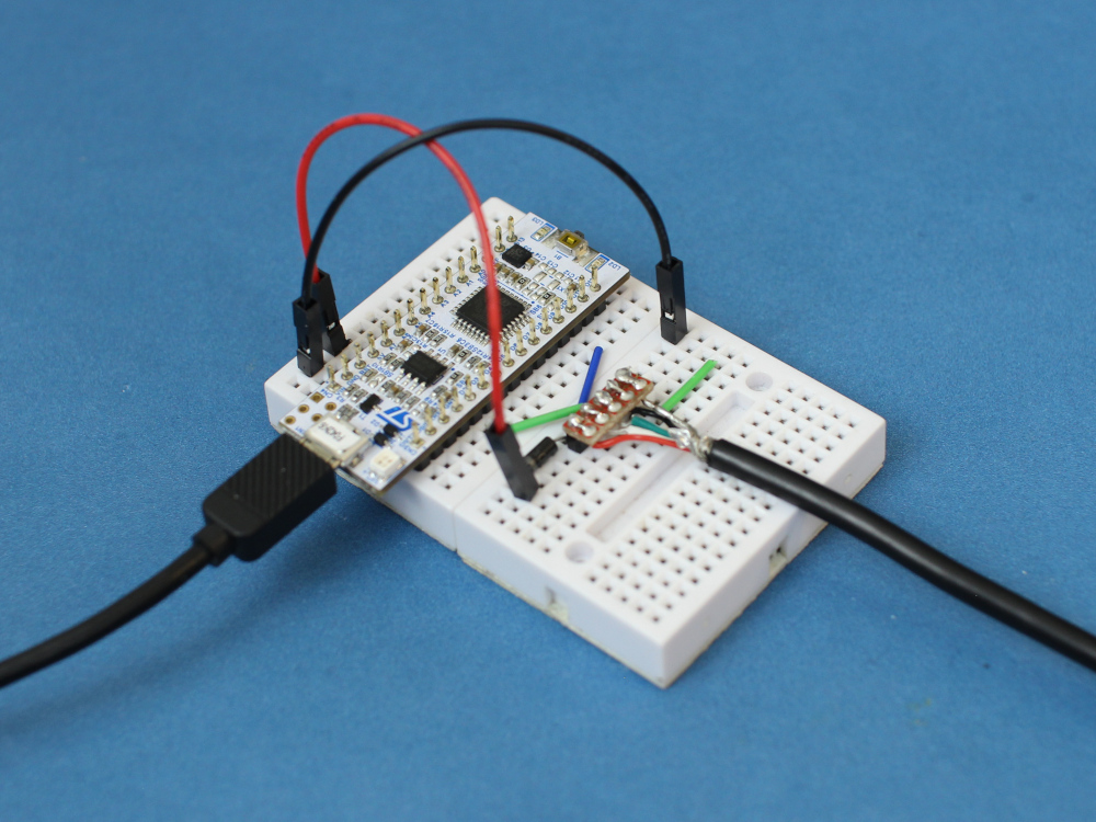
To begin, strip a USB cable or get a USB breakout board (like this one from SparkFun) and connect the lines to a breadboard as shown in the Fritzing diagram below. Make the following connections:

  • VUSB → Diode → Nucleo 5V (don’t want to short something if we’re plugging in 2 USB cables!)
  • USB D- → Nucleo D10 (PA11)
  • USB D+ → Nucleo D2 (PA12)
  • USB GND → Nucleo GND
  • USB GND → USB Shield (don’t know if this is necessary, but it makes me feel better)

Also, this is super important: remove the jumper that comes default on your Nucleo board! It bridges D2 and GND and will short out our D+ line if left in place.

Connecting an STM32 Nucleo board to USB for VCP

Plug the two USB cables from the Nucleo board into your computer. We’ll be sending our compiled program over to the ST-LINK side of the board, and the VCP will enumerate on the USB lines that we just added. I don’t have a bootloader working (yet) to where we can send binary files over VCP, but that’s on my to-do list.

Nucleo-32 connected to a USB for VCP

For this, I’m using STM32CubeIDE along with the STM32F0 HAL API.

In STM32CubeIDE, start a new project (File > New > STM32 Project). Choose your part or board. I’ll pick the Nucleo-F042K6, since that’s the board I have.

STM32CubeIDE part selector

On the next screen, give your project a useful name (such as “nucleo-f042k6-vcp-test”). Leave everything else as default. We’ll be using C as our language for this example. Click Finish, and you’ll be asked a few questions:

  • Yes to “initialize all peripherals with their default Mode”
  • Yes to “open this perspective now”

In the CubeMX configuration perspective, you’ll need to enable a few options to initialize the USB as a Virtual COM Port. In the Pinout & Configuration tab, go to Categories > Connectivity and click USB. Enable Device (FS). You should see PA11 and PA12 be automatically configured for USB_DM and USB_DP.

STM32CubeIDE selecting USB

Under Categories > Middleware, select USB_DEVICE. Change Class For FS IP to Communication Device Class (CDC). This tells the USB stack that we want to enumerate as a CDC device, which will allow us to send serial data to and from our computer across the USB lines.

Select USB CDC

Click on the Clock Configuration tab. The software will tell you that your clocks have issues. By default, the Nucleo-F042K6 board is configured for 8 MHz clocks for almost everything. We need to bump those up to 48 MHz for USB to work. Luckily, you can just click Yes on the pop-up when asked to run the automatic clock issues solver. This should automatically change all of the necessary clocks to 48 MHz.

Updating clock speeds to match USB

In the Project Manager tab, change the Minimum Heap Size to 0x100. The STM32F042K6 comes with 6 kB of RAM, which isn’t a whole lot. USB functionality takes up probably 2-3 kB worth of that memory, so we need to be careful about how we use the rest.

We can free up some space by adjusting the minimum heap and stack sizes. These parameters essentially reserve sections of data memory for the heap and stack. By setting 0x200 and 0x400, we’ve told the processor to reserve 1 kB of RAM for the heap and stack, respectively. We need to lower one of them in order to accommodate the USB functions. I chose heap, as it seems less likely we’ll be using dynamically allocated memory for this application.

If you get an error message like `._user_heap_stack’ will not fit in region `RAM’  or region `RAM’ overflowed by 64 bytes  when you compile, it means you are running out of RAM in your application. You will need to go into the Device Configuration Tool (the .ioc file) and adjust the stack and heap settings as described above. Alternatively, you can go into the .ld linker script and look for the _Min_Heap_Size  and _Min_Stack_Size  settings there (just know that this file will be overwritten if you make changes in the graphical Device Configuration Tool).

Allocate minimum heap size in STM32CubeIDE

Click File > Save to save the changes to the CubeMX configuration. You’ll be asked if you want to generate Code. Click Yes.

In your project files, navigate to the Src directory. Notice that you have several USB-related files that have been added. usbd_cdc_if.c contains the functions that allow us to send and receive serial data using the USB Communication Device Class. Feel free to peek in there, if you wish.

Open up Src > main.c. At the top, under /* USER CODE BEGIN Includes */ , enter the following line:

#include "usbd_cdc_if.h"

This will let us call functions from the CDC library. Scroll down to our while(1) loop in main. Under /* USER CODE BEGIN 3 */  (but still inside the while loop), enter the following:

uint8_t buffer[] = "Hello, World!\r\n";
CDC_Transmit_FS(buffer, sizeof(buffer));
HAL_Delay(1000);

Here, we create a simple string and call a USB CDC function to send out that string over the USB lines. We then wait for 1 second before repeating this action ad infinitum.

Code to transmit a string over a serial VCP via USB CDC in STM32

Click Project > Build All to build the project. Click Run > Debug As > STM32 MCU C/C++ Application. A pop-up window will appear asking you to create a new launch configuration. Note that if you are not using a Nucleo board or an ST-LINK, you can change the hardware debugger (e.g. to a Segger J-LINK) in the Debugger tab. If you are using a Nucleo, leave everything as default and click OK.

New STM32 debug configuration

If asked to switch to the Debug perspective, click Switch. When the new perspective opens, click Run > Resume (or the play button on the toolbar).

Debugging in STM32CubeIDE

Your code should now be running, and the microcontroller will enumerate as a USB device! Feel free to verify the new serial port in your OS’s device manager. This should show up as a USB serial or COM port.

STM32 as a USB serial (COM) port

Open your favorite serial terminal program, and enter the following connection details:

  • Port: USB serial or COM port discovered above
  • Baud rate: 9600
  • Data bits: 8 (default)
  • Parity: None (default)
  • Stop bits: 1 (default)

Setting serial terminal to listen for STM32

Open the serial connection, and you should be greeted by that oh-so-familiar phrase, repeating over and over again:

STM32 outputting strings via serial COM port on USB

When you’ve had enough strings, feel free to press the stop button in the IDE to stop the program from running on the STM32.

Interestingly enough, the STM32 seems to support autobaud detection by default. Try changing the serial terminal’s baudrate to anything else and see if you can still receive text. I bet that disabling autobaud would save some RAM, but I have not discovered how yet.

From what I understand, CDC_Receive_FS() is a callback, so you’ll need to change its definition in usbd_cdc_if.c to get it to work. I haven’t played with it yet, so that’ll be a post for another time.

I hope that this helps you get started with your STM32 USB journey!