NVIDIA Jetson Orin Nano

Getting Started with NVIDIA Jetson Orin Nano
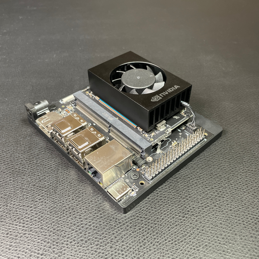
The NVIDIA Jetson Orin Nano is a powerful single-board computer built with an NVIDIA Ampere GPU for performing a variety of parallel-operation tasks, like cryptocurrency mining and AI. In this guide, we will walk you through the process of flashing NVIDIA’s Ubuntu image to the Orin Nano Development Kit.

The Jetson Orin Nano Developer Kit Getting Started Guide defaults to flashing an SD card with the pre-configured Ubuntu image (similar to how you might configure a Raspberry Pi). This has 2 issues:

  1. The SD card is much slower and offers less space than an NVMe M.2 SSD. If you are working with large AI models, I highly recommend purchasing and mounting an SSD in one of the available M.2 slots under the dev kit.
  2. Jetpack 6.0+ (with the newest Ubuntu OS) contains updated QSPI drivers. If you try to flash the SD card, you will likely find that your Orin Nano simply boots to a blank screen due to the outdated drivers. As a result, you must use the NVIDIA SDK Manager from a host computer to flash the OS directly to the dev kit (i.e. over a USB cable) the first time. See this post for more information.

To ensure that you can flash to either SSD or SD card as well as have the most up-to-date drivers, I recommend using the SDK Manager to flash directly to the board. The rest of this guide will show you how to use the SDK Manager to flash Ubuntu to the Orin Nano dev kit.

Required Hardware

You will need the following hardware:

Insert the SD card on the underside of the Orin Nano (you can see the SD card slot between the Orin Nano card and carrier board) or attach the SSD to the underside of the dev kit carrier board. Connect keyboard, mouse, and monitor if desired. Note that the USB C connector (not the USB A ports) contains an Ethernet pass-through, which means you can SSH into the board via USB if you don’t want to connect other peripherals.

Install and Run Required Host Operating System

To flash the operating system (OS) onto the Orin Nano, you should use the NVIDIA SDK Manager running from a host computer. In my experience, you absolutely must use the supported host operating system to run the SDK Manager. See the supported OS chart on the SDK Manager page to figure out which host OS you need to use. For this guide, we will use the SDK Manager to install JetPack 6.0, which means we must use exactly Ubuntu 20.04 or Ubuntu 22.04 (not Linux Mint or any other derivative–it must be the official Ubuntu distro).

If you happen to be running either Ubuntu 20.04 or Ubuntu 22.04, great! If not, I recommend creating a bootable USB drive that you can use to try Ubuntu without installing it.

  1. Download ubuntu-22.04.4-desktop-amd64.iso from this page
  2. Follow these instructions to create a bootable USB drive with the Ubuntu image

Boot your host computer into Ubuntu 22.04 from the USB drive. Note that you may need to adjust the boot order or permissions in your BIOS.

Install NVIDIA SDK Manager

The SDK Manager is a program that allows you to install operating systems, libraries, and additional software onto a connected NVIDIA single-board computer.

Boot and log into your host OS (Ubuntu 22.04, if you followed the above instructions). Open Software & Updates and enable Community-maintained free and open-source software (universe) and Proprietary drivers for devices (restricted) options.

Open a browser and navigate to https://developer.nvidia.com/sdk-manager. Click the .deb Ubuntu link at the top-right of the page to download the latest SDK Manager package. Take a look at the filename of the .deb file you just downloaded. It will contain version and build numbers, which we need for the next step. For example, if the file is named sdkmanager_2.1.0-11669_amd64.deb, then the version is 2.1.0 and the build is 11669.

Open a terminal and install some dependencies:

sudo apt update
sudo apt install -y libcanberra-gtk-module

From there, install the .deb package (replace [version] and [build] with the version and build numbers in the actual filename):

sudo dpkg -i sdkmanager_[version]-[build]_amd64.deb

Connect Orin Nano

To flash the Orin Nano using the SDK Manager, it must first be put into “recovery mode.” To do that, attach a jumper or jumper wire between the FC_REC and GND pins (pins 2 and 3) on the underside of the Orin Nano card.

Connect a cable between the USB-C port on the dev kit and a USB port on your host computer. Plug the power adapter into the dev kit.

In a terminal on the host computer, enter the following command:

lsusb

You should see ID 0955:7523 NVIDIA Corp. APX as one of the items. This ID and name is important! If you do not see this ID/name, it means the board is not in recovery mode, not connected, or not powered. The SDK Manager looks for this exact name to find the board in recovery mode.

Flash OS With the SDK Manager

Enter the following command to run the SDK Manager:

sdkmanager

You should be presented with a new SDK Manager window. Click Login in to bring up a browser and log in to your NVIDIA account (create one if you do not already have one).

If you get a pop-up in the SDK Manager asking you to select a board, select Jetson Orin Nano [8GB developer kit version] and click OK.

Next, select the latest JetPack (6.0 for me), and select any additional SDKs, like DeepStream, if required (none for me).

Click Continue. Add additional components as needed. In theory, you should be able to download/install these components on the Jetson board once you have it up and running.

Note that the SDK Manager will download a LOT of data! You’ll need ~50 GB of free space to make this all happen:

  • If you’re running Ubuntu natively and have the available space, just leave the target locations as their defaults.
  • If you are running from an Ubuntu Live USB/CD and don’t have the space to download everything, mount additional storage and change the Download folder and Target HW image folder locations (as I have done in the image below). Note that you might need to re-mount the drives in read/write mode. You must use a partition formatted with ext4, as the installation script attempts to use Linux permissions when configuring files/executables.

Click Continue and wait. And wait. And wait. You’ll download a lot of data.

After the download is done, select any desired SDK components you might want for development (you can install them later from the Orin Nano if you wish). I left mine at the defaults. You will also be asked where you would like to flash the OS and SDK components:

  • Selected device: Jetson Orin Nano [8GB developer kit version]
  • OEM Configuration: Runtime (this will run System Configuration Wizard on first boot)
  • Storage Device: choose SD card or SSD (depending on what hardware you installed)

Note: If you chose Pre-config for OEM Configuration, you will be asked to provide username/password details to configure the Orin Nano OS. It will skip the System Configuration Wizard on first boot, which means you don’t need to attach a keyboard, mouse, and monitor to finish the installation process.

Click Flash. Wait some more. Eventually, the Orin Nano should boot, and you should be presented with the Ubuntu System Configuration Wizard

When finished with the configuration wizard, log in to Ubuntu. At this point, the USB-C port will expose an ethernet port (l4tbr0) with the default IP address of 192.168.55.1. That means you can ping or SSH into your Orin Nano over USB (e.g ssh [username]@192.168.55.1).

Shut down the Orin Nano and remove the power adapter. Remove the “Recovery Mode” jumper.

Run the Orin Nano

Attach the power adapter to the Orin Nano and wait for it to boot. You should be presented with a login screen. Enter your username and password to start using Ubuntu!

Troubleshooting

If the SDK Manager gives you any trouble (like making it so you can’t change the download folders), you can close the SDK Manager and delete the cache. Note that you will need to re-login once you start the sdkmanager again.

rm -rf ~/.nvsdkm/
rm -rf ~/Downloads/nvidia
sdkmanager

If the SDK fails on download/install, check the logs. If you see the error chroot: failed to run command 'dpkg': Exec format error it means that qemu is not installed or running correctly (see here for more info). Run the following commands and restart the SDK Manager.

sudo apt-get install qemu-user-static
sudo update-binfmts --import qemu-aarch64

Going Further: Local LLM

The Orin Nano contains a powerful (for its size) GPU, but it means carefully installing and configuring software to take advantage of that GPU. If you want to run a local LLM (think ChatGPT, but smaller), check out these great tutorials on the NVIDIA Jetson AI Lab site.

In a future post, I will show how to install Ollama and Piper-TTS on the Orin Nano to run my hopper-chat project for a complete voice assistant.

Raspberry Pi Pico

How to Build OpenOCD and Picotool for the Raspberry Pi Pico on Windows
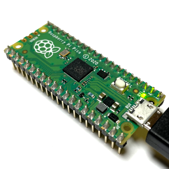
This tutorial will show you how to use Windows to build the Raspberry Pi Pico version of OpenOCD and picotool used to debug programs on the RP2040.

Chapter 5 and Appendix B of the Getting Started with Raspberry Pi Pico PDF talk about how to build these tools. However, they focus mostly on building the tools for Linux and maxOS. Understandably, building tools on these operating systems is easier, but we can still build them on Windows.

Note that you have the option of skipping the steps below and downloading the executables that I created here. If they do not work or you don’t trust them (no hard feelings), you can continue with the steps below to build your own OpenOCD and picotool.

Directory Setup

I recommend following the steps in my first Raspberry Pi Pico on Windows tutorial to set up the RP2040 build system. We will use the directory structure in that tutorial to hold the source code and executables for these tools.

Specifically, you will want to check out the repositories mentioned in this tutorial into C:\VSARM\sdk\pico.

Install Git for Windows SDK

Git for Windows SDK is different than Git for Windows, as the former contains a number of tools that help us build programs on Windows (including a package manager). Regular Git Bash does not have these features.

Head to https://gitforwindows.org/#download-sdk and download Git for Windows SDK. Download the latest installer for your version of Windows (likely the 64-bit version).

Run the installer, accepting all the defaults. This will open a command prompt window and begin to download/install Git for Windows SDK. It will take some time, as it’s a rather large set of files.

Installing Git for Windows SDK

Note that Git for Windows SDK installs (by default) in C:\git-sdk-64. This directory contains everything as part of the SDK, which means you can delete the directory when you are done using it.

Install Packages

One of the best features of Git for Windows SDK is the pacman package manager. It allows you to install libraries and software similar to how you might do it in Linux.

Run C:\git-sdk-64\git-bash.exe. Note that you must use this executable to run Git for Windows SDK and not the one you may have installed in the previous tutorial! The window should say “SDK-64:/” at the top if you’re running the correct version.

In the terminal, enter the following commands:

pacman -Syu 
pacman -Su
pacman -S mingw-w64-x86_64-toolchain git make libtool pkg-config autoconf automake texinfo wget

When pacman asks which members to install in the mingw-w64-x86_64-toolchain, press ‘enter’ to install all.

Install packages in Git for Windows SDK

When asked “pkg-config and pkgconf are in conflict. Remove pkgconf? [Y/n],” enter Y.

When asked “Proceed with installation? [Y/n],” enter Y again.

This will take some time to download and install all of the packages.

Note: there is an issue with libusb-1.0.24 on MSYS2. We will manually install v1.0.23 to prevent the segmentation fault from occurring when running OpenOCD or picotool. If you run pacman -Su to update packages after this manual installation process, it will remove version 1.0.23 and update libusb to the latest (1.0.24 at the time of writing). For more information, see this forum post.

Enter the following commands to install libusb-1.0.23:

cd ~/Downloads
wget http://repo.msys2.org/mingw/x86_64/mingw-w64-x86_64-libusb-1.0.23-1-any.pkg.tar.xz
pacman -U mingw-w64-x86_64-libusb-1.0.23-1-any.pkg.tar.xz

Enter Y when asked “Proceed with installation? [Y/n].”

Installing libusb

At this point, we’re ready to build our tools!

Build OpenOCD

OpenOCD (Open On-Chip Debugger) is an open-source tool that communicates with GDB to send commands over JTAG or SWD to a number of different microcontrollers. The RP2040 is not officially supported in OpenOCD at the time of writing, so we need to build a special branch of OpenOCD.

In your Git for Windows SDK terminal, enter the following commands:

cd /c/VSARM/sdk/pico
git clone https://github.com/raspberrypi/openocd.git --branch picoprobe --depth=1
cd openocd
./bootstrap
./configure --enable-picoprobe --disable-werror
make

When OpenOCD is done building, you will need to copy in the libusb-1.0.dll library file from your Git for Windows SDK directory. This .dll file must be in the same directory as your openocd.exe file for the tool to work. If you move openocd.exe, you’ll need to copy libusb-1.0.dll to the same folder.

Enter the following command to copy the file into the current directory:

cp /c/git-sdk-64/mingw64/bin/libusb-1.0.dll src/libusb-1.0.dll

You can test running OpenOCD with the following command:

src/openocd.exe

You should expect it to throw some errors and exit, as we haven’t given it any parameters.

Testing OpenOCD

Note: I do not recommend calling make install as shown in the Getting Started guide! This will make the Pico version of OpenOCD the default OpenOCD for your whole system. If you plan to use OpenOCD for other embedded debugging, you’ll want to keep the Pico version separate. For now, just leave the executable in the src folder. You can call this executable explicitly from the command line or set VS Code to use it on a per-project basis.

Build Picotool

Picotool is a program used to inspect RP2040 binaries and interact with the RP2040 in bootloader mode.

Note that to build picotool, you will need to have the SDK_PICO_PATH environment variable set to the location of your pico-sdk (e.g. C:\VSARM\sdk\pico\pico-sdk) as we did in the previous tutorial.

Open C:\git-sdk-64\git-bash.exe (if it’s not already open).

Run the following commands to clone the picotool repository and build it:

cd /c/VSARM/sdk/pico
git clone -b master https://github.com/raspberrypi/picotool.git
cd picotool
mkdir build
cd build
cmake -G "MinGW Makefiles" -DPC_LIBUSB_INCLUDEDIR="/c/git-sdk-64/mingw64/include/libusb-1.0" ..
make

Just like with OpenOCD, we’ll need a copy of libusb-1.0.dll to be in the same folder as picotool.exe. Enter the following command to copy it into the build folder:

cp /c/git-sdk-64/mingw64/bin/libusb-1.0.dll .

We also need a copy of libgcc_s_seh-1.dll:

cp /c/git-sdk-64/mingw64/bin/libgcc_s_seh-1.dll .

You can test picotool by entering the following:

./picotool.exe

It should spit out a help message and exit.

Testing picotool

Optional: You can add picotool.exe to your Path, if you feel so inclined. This will allow you to call “picotool” from any terminal.

  1. Search for “environment variables” in the Windows search bar
  2. Open “Edit the system environment variables”
  3. Click “Environment Variables…”
  4. Select Path under “User variables” and click “Edit…”
  5. Add a new entry: C:\VSARM\sdk\pico\picotool\build (or whever you’re keeping picotool.exe)
  6. Click OK on all the windows to save the settings

Note: At the time of writing, I could only get this build of picotool to run inside of Git Bash. I’m assuming that the MinGW environment is somehow necessary for its execution. If I find a way to make the .exe run in Command Prompt or PowerShell, I will post it here.

Update Driver

Windows does not have a native driver to send commands over USB to the Pico from picotool. So, we have to install one manually.

Put your Pico board into bootloader mode (press and hold BOOTSEL and plug in the USB cable). It should enumerate on your computer as a storage drive.

Head to https://zadig.akeo.ie and download Zadig.

Run Zadig. Select Options > List All Devices.

You should see 2 Pico devices in the drop-down menu: RP2 Boot (Interface 0) and RP2 Boot (Interface 1). Select RP2 Boot (Interface 1).

The driver should be listed as (NONE). Select libusb-win32 (some version) as the replacement driver.

Install USB driver with Zadig

Click Install Driver. When it’s done, the current driver should be listed as “libusb-win32.”

If you break something in Zadig (like I did), you can fix it. For example, the Pico will not enumerate as a mass storage device drive in bootloader mode. Zadig will show something other than “USBSTOR” as the driver for RP2 (Interface 0). Here is how to delete the bad drivers and let Windows fix the mess you made:

  1. Put Pico into bootloader mode
  2. Open Device Manager
  3. Click View > Devices by container
  4. Expand RP2 Boot
  5. For all entries under RP2 Boot:
    • Right-click on entry
    • Select Uninstall Device
    • Check “Delete the driver software for this device” (if asked)
    • Click Uninstall
  6. Unplug Pico
  7. Hold BOOTSEL and plug it back in to put it into bootloader mode again
  8. Windows should automatically reinstall all the correct drivers

Test Picotool

With your Pico in bootloader mode, enter the following command:

/c/VSARM/sdk/pico/picotool/build/picotool.exe info

Note that you can run picotool without specifying the path name if you added its location to your Path.

If it is able to communicate with your connected Pico, you should see that printed.

Testing picotool

Going Further

Once you have finished building OpenOCD and picotool, you can uninstall Git for Windows SDK by simply deleting the C:\git-sdk-64 directory.

Hopefully, this has helped you get started with some advanced tools for programming and debugging on your Raspberry Pi Pico. If you would like to set up step-through debugging using VS Code, see this tutorial (link coming soon).

Happy hacking!

How to Set Up Raspberry Pi Pico C/C++ Toolchain on Windows with VS Code
This tutorial will show you how to install the Raspberry Pi Pico toolchain on Windows 10 for C and C++ development.

Raspberry Pi has a fantastic getting started guide for the Pico that covers installation steps for the major operating systems. On Linux (specifically, most flavors of Debian), you can run a single script that will install everything for you. On macOS, you need to use Homebrew to install the toolchain, which is only a few commands in the terminal.

Windows, however, is a different story. Installing the toolchain is an arduous process, requiring multiple programs and manually modifying the Windows Path. The Raspberry Pi Pico getting started guide shows you how to do this, but I have issues with two parts: you need to install Build Tools for Visual Studio (around 6 GB) and you must run VS Code from within a Developer Command Prompt every time.

This guide walks you through an alternative way of installing the C/C++ toolchain for the Pico, using MinGW in place of the Build Tools for Visual Studio. Note that this guide is meant for intermediate/advanced users; it assumes you have some familiarity with environment variables in Windows and CMake.

Important! There are a lot of steps in this guide, and missing one will likely cause things to fail down the road. Take your time, and slowly perform each step in order. I recommend setting aside around 2 hours to complete the setup. If something does not work, return to earlier sections to ensure you performed each step correctly. Don’t ignore errors! Something that did not install correctly likely means the tool won’t work later.

[Update Sep 27, 2024] This guide still technically works if you use Windows Command Prompt to run CMake and Make. If you use Git Bash, you’ll likely get the error: mingw32-make[2]: *** [CMakeFiles\blink.dir\build.make:1341: blink.elf] Error -1073741819. I have not yet figured out how to solve this issue. As an alternative, you might want to try the official Raspberry Pi Pico VS Code plugin: https://github.com/raspberrypi/pico-vscode.

Directory Setup

With the exception of CMake and Python, we will want all of our tools and SDK files to exist in one folder on Windows. This setup will make it easy to configure the Path and find things later on.

Create a folder named VSARM in the top level of your C drive.

In C:\VSARM, create the following folders:

  • C:\VSARM\armcc
  • C:\VSARM\lib
  • C:\VSARM\mingw
  • C:\VSARM\sdk

Note that this directory structure is similar to how you might set up other Arm compiler tools and SDKs (such as this STM32 toolchain setup). You should be able to keep all of your Arm development tools in the VSARM directory and have them coexist with other tools and SDKs.

We use these short, one-word folder names to keep paths short and to avoid spaces. Some Unix/Linux tools (that have been ported to Windows) do not work well with paths that have spaces in them.

Install GNU Arm Embedded Toolchain

The GNU Arm Embedded Toolchain contains the Arm GCC compiler that we need to compile C and C++ code for the RP2040.

Head to the GNU Arm Embedded Toolchain download page and download the latest installer for Windows. For me, this was gcc-arm-none-eabi-10-2020-q4-major-win32.exe.

[Update Apr 19, 2022] I have verified that Arm GNU Embedded Toolchain 11.2-2022.02 works.
[Update Sep 27, 2024] The Arm GNU Toolchain download page has moved here. Download the AArch32 bare-metal target (arm-none-eabi) executable (.exe) for your operating system (Windows host in this case). I have verified that this guide still works with arm-gnu-toolchain-13.3.rel1-mingw-w64-i686-arm-none-eabi.exe.

Run the installer. When asked, change the installation location to C:\VSARM\armcc. It will auto-fill the destination directory to the name of the current toolchain release.

Installing GNU Embedded Toolchain on Windows

Continue with the installation process. When it is complete, select the option to Add path to environment variable.

Add Arm GCC to Windows path during installation

At this point, you should be able to call any of the Arm compiler tools in a new command prompt, such as arm-none-eabi-gcc.exe.

Install MinGW-w64 GCC Tools

MinGW (short for Minimalist GNU for Windows) is a collection of open-source utilities, such as compilers and linkers, that allow us to build applications for Windows.

When we build Pico projects, we need to compile the elf2uf2 and pioasm tools from source. These tools run on our computer (not the target RP2040 microcontroller), and we need a native compiler and linker. The original Getting Started guide has us install Build Tools for Visual Studio to get a Windows compiler (cl.exe), linker (link.exe), and make tool (nmake.exe). We’re going to use the open-source GNU suite (e.g. gcc, ld, make) for Windows instead.

[Update Apr 19, 2022] Note: at this time, the MinGW (.exe) installer appears to be broken. You will likely see the error message “The file has been downloaded incorrectly!” As a result, I have updated the portion below to download only the MinGW-W64 GCC files (tested with v8.1.0), as that’s all we need to compile Pico programs (this no longer applies, as I have updated the instructions–see Sep 27, 2024 update).

[Update Sep 27, 2024] The SourceForge files have been reorganized, and you can no longer find the pre-compiled binaries for Windows (at least for newer versions of MinGW). As a result, I have updated the instructions below to show how to work with the latest version of MinGW (14.2.0 at the time of writing).

Head to https://github.com/niXman/mingw-builds-binaries/releases, which hosts the latest, pre-compiled binaries for MinGW. Download the x86_64-X.X.X-release-win32-seh-ucrt-rt_vY-revZ.7z (where X.X.X, Y, and Z are the respective release, version, and revision numbers). This was tested with: x86_64-14.2.0-release-win32-seh-ucrt-rt_v12-rev0.7z.

Unzip the file into the C:\VSARM\mingw directory. Windows 11 should be able to handle .7z files natively now. If not, you can download the 7-zip utility. Uncheck the named unzip directory so that when everything unzips, you should have C:\VSARM\mingw\mingw64.

When it’s done, open a Windows Command Prompt and enter the following into the terminal:

echo mingw32-make %* > C:\VSARM\mingw\mingw64\bin\make.bat

This creates a wrapper batch file that will call the mingw32-make tool whenever you type make into a Windows terminal. We will update the Windows Path to find all of the tools in mingw64\bin (along with this .bat file) in a later step.

Install CMake

CMake is a tool that helps you automate the build process of programs. It does not build/compile (like Make does), but rather, it can generate the directory structures and files needed for any build system (Make, Qt Creator, Ninja, etc.). The Raspberry Pi Pico SDK relies on CMake to help create these build files.

Head to the download page on CMake’s site.

Important! There is a bug in CMake version 3.20 (at the time of writing). On the second run of make or nmake (after running cmake), the process will fail. If you’re using nmake, you’ll get an error like fatal error U1033: syntax error : ':' unexpected,  or if you’re using mingw32-make, something like *** multiple target patterns. Stop. To prevent this, install CMake version 3.19. Future versions of CMake may fix this bug, but for now, know that version 3.19 worked for me.

[Update Apr 19, 2022] I have verified that CMake 3.23.1 now works. The bug has been fixed.

Download the latest installer for Windows (cmake-3.30.4-win64-x64.msi as of Sep 27, 2024).

Run the installer and accept the user license. On Install Options, select Add CMake to the PATH environment variable.

Installing CMake 3.30.4

Continue the installation process, accepting all the defaults. Note that this will install CMake to C:\Program Files\CMake, which is fine, as it will be used as a system-wide tool (not just for VSARM projects).

Install Python

The Pico SDK relies on Python to script and automate some of the build functions.

Important! At the time of writing, the Pico SDK recommends Python version 3.9. I do not know if other versions will work.

[Update Apr 19, 2022] I have verified that Python 3.10.2 works.

[Update Sep 27, 2024] I have verified that Python 3.12.6 works.

Head to the downloads page on the Python site. Download the latest Python 3.9 (or 3.10) installer.

Run the installer. On the first screen, make sure that Install launcher for all users (recommended) is checked and check Add Python to PATH.

Add Python to Windows PATH

Click Install Now and wait while it installs Python.

At the end of the installation process, select the option to disable the path length limit.

Important! If you were not asked to disable the MAX_PATH length limit, you will want to make sure that long paths are enabled. The Pico SDK (and many other SDKs) often have long, nested folders, resulting in pathnames that exceed the original Windows limit (260 characters).

To enable long paths, search for regedit in the Windows search bar and run the Registry Editor program. Navigate to Computer\HKEY_LOCAL_MACHINE\SYSTEM\CurrentControlSet\Control\FileSystem and add an entry (if one is not already there) for LongPathsEnabled. Change Value data to 1 and Base to Hexadecimal.

Disable pathname character limit in Windows registry

Here is a full guide if you need help modifying the registry to disable the pathname limit.

Install Git

Git makes downloading the Pico SDK much easier, and the Windows version comes with Git Bash, which is a super useful shell. We can change the shell in VS Code to Git Bash so that the command line works just like in Linux. Note that you will need Git installed (with or without Git Bash), as some of the CMake commands require it when configuring a project.

Head to the Git SCM download page and download the latest installer for Windows (e.g. 32-bit Git for Windows Setup).

Run the installer. When you get to the screen asking you to choose a default editor, feel free to pick whatever you want. I kept vim because I know it (barely) well enough to edit git comments.

Select default editor for Git on Windows

Continue the installation process, accepting all the defaults.

Download Pico SDK and Examples

The Pico SDK conains a collection of tools and libraries used to make developing on the Pico (and RP2040) much easier. We can also download a set of C/C++ examples that are useful demonstrations of how to use the SDK.

To start, create a new folder named pico in C:\VSARM\sdk.

While you could download the .zip versions of the SDK and examples repositories, it’s much easier to use git. There are nested submodules that you would need to download from other repositories, but one command in Git Bash takes care of that for us.

Open Git Bash and enter the following commands.

cd /c/VSARM/sdk/pico 
git clone -b master https://github.com/raspberrypi/pico-sdk.git 
cd pico-sdk 
git submodule update --init 
cd .. 
git clone -b master https://github.com/raspberrypi/pico-examples.git

Download Pico SDK and examples

At this point, you should have all of the necessary build tools, SDK, and examples installed to start developing programs for the Raspberry Pi Pico and RP2040.

Update Environment Variables

Some of the tools we installed automatically updated the Windows environment variables (specifically, the Path). However, a few (like MinGW and the SDK) did not. We need to update the environment variables so that the shell and various build tools know where to find things in our filesystem.

In the Windows search bar, enter env. Click on Edit the system environment variables.

In that window, click on Environment Variables…

Under User variables for <username>, select Path and click Edit.

Add C:\VSARM\mingw\mingw64\bin as a new entry. This will allow us to use things like gcc and ld to build C and C++ programs for Windows.

Make sure you see the following entries listed:

  • C:\VSARM\armcc\<release version>\bin
  • C:\VSARM\mingw\mingw64\bin

You might see an entry for Python3x (e.g. Python39 or Python312) if you chose to install Python for the current user (as I did).

Add mingw32 to user path environment variable

Click OK to exit the user Path window.

Under User variables for <username>, click New… and add the following entry:

  • Variable name: PICO_SDK_PATH
  • Variable value: C:\VSARM\sdk\pico\pico-sdk

Click OK to save the environment variable. At this point, your User Variables should have an updated Path as well as PICO_SDK_PATH variables.

Updating environment variables in Windows for Pico SDK

Under System variables, select Path and click Edit. Check to make sure you see the following entries (add them if you do not see them):

  • C:\Program Files\CMake\bin
  • C:\Program Files\Git\cmd

These entries should have been automatically added to your system-wide Path when you ran their installers. You might also see an entry for Python39 (or Python312) if you chose to install Python for all users.

Click OK on all 3 of the open windows to close them and save changes.

At this point, you should be able to open a commend prompt and enter commands like gcc, make, and echo %PICO_SDK_PATH% to make sure the environment variables were set correctly.

Trying various mingw commands in Windows terminal

Install VS Code

Visual Studio Code (VS Code) is a great, cross-platform text editor that offers highly configurable plugins. With the right plugins, you can essentially turn VS Code into a full-fledged integrated development environment (IDE) with step-through debugging! I’ll only show the basics for now so you can get your VS Code on Windows to act like VS Code on other operating systems when working with the Pico.

Head to code.visualstudio.com and download the latest release for Windows.

Run the installer and accept all of the defaults. You’re welcome to create a desktop icon and add “Open with Code” to the Windows Explorer context menu. I like to enable these options, but they’re not necessary.

Enable custom options in VS Code installation

When the installer is done, it’s time to test building a program for the Pico.

Build Blink Example

You should be able to build Pico code from any command prompt at this point. However, we’re going to do so in VS Code to show how it might be done during development.

Open VS Code. Click Terminal > New Terminal. The default terminal that opens is likely Windows PowerShell. I recommend changing this to Git Bash (or WSL) by clicking on the drop-down menu and selecting New Git Bash.

Just like we did with the make.bat file (for Windows terminals), I recommend creating an alias for mingw32-make.exe in Git Bash. Enter the following commands (you will only need to do this once):

echo "alias make=mingw32-make.exe" >> ~/.bashrc
source ~/.bashrc

Build the blink example by entering the following commands into your terminal:

cd /c/VSARM/sdk/pico/pico-examples/
mkdir build
cd build
cmake -G "MinGW Makefiles" ..
cd blink
make

Important! Any time you call CMake from a terminal like this, you will need to specify “MinGW Makefiles” as the build system generator (-G option).

Build Raspberry Pi Pico blink example in VS Code

This should build the blink example and generate the .elf, .hex, and .uf2 binary files. We can easily upload the .uf2 file to our Pico without any special tools.

Put the Pico board into bootloader mode (press and hold the BOOTSEL button while plugging a USB cable into the Pico).

Find which drive letter the RPI-RP2 drive is mounted to (e.g. it was G: for me). Enter the following into Git Bash (change the drive letter as necessary):

cp blink.uf2 /g/

Your Pico board should be blinking away!

Raspberry Pi Pico blinking

I hope this has helped you get started using the Raspberry Pi Pico SDK on Windows! I personally found that relying on MinGW for the compiler tools was easier than using Build Tools for Visual Studio.

From here, you can set up VS Code any way you like with various plugins like CMake Tools. I did not cover setting up debugging and other tools (picotool, gdb, OpenOCD, etc.), which are topics for another time. For now, I recommend referring to the Pico C/C++ Getting Started Guide to see how to configure those tools in VS Code.

Happy hacking!

[Update May 23, 2021] Since posting this, I have made a video (for Digi-Key) that shows you how to use VS Code plugins for one-click CMake and building. You can see that video here.

custom wake word cover

Custom Wake Word Part 1: Capturing Data

One of the biggest complaints about many home assistants (like the Amazon Echo) is the inability to create custom wake words. Sure, you can select from a list of pre-existing wake words, but to create your own is quite a technical challenge. Sometimes, it might be fun to say something other than “Alexa” or “OK Google.”

I want to create a multi-part series on how you might go about creating custom wake words (also known as a “hotword”). These tutorials will show you how to collect voice samples and train a simple machine learning model (neural network) to use on any number of devices, including single board computers (e.g. Raspberry Pi) and microcontrollers (e.g. Arduino).

This first tutorial will demonstrate one possible way to collect voice samples necessary for training your model. If you would like to see me discuss data collection and why I’m doing this project, see this video:

Why You Need to Capture Data for Your Custom Wake Word

Unfortunately, you can’t just say a word a couple of times and train a neural network to recognize that word. Computers are still not quite as capable as toddlers.

Even if you said a word 100 times, the neural network would likely learn features of your voice rather than the word itself. After that, every time you said something even remotely close to the wake word, the model would label it as the wake word.

To remedy this, we need lots of different types of people with different types of voices saying the same word (and with different inflections). With hundreds or thousands of different training examples, the neural network will hopefully learn the features that uniquely make up that word rather than your particular voice.

Companies that make voice assistants have their own methods of capturing voice samples. For example, Google scrapes millions of YouTube videos to create audio training sets for sounds and voices. Here is an example of one such set you can use in your training. Note that these are “human-labeled,” meaning Google likely paid lots of people to listen to lots of audio clips and assign a label to each one.

Another way to collect voice data is by crowd-sourcing. We can do that by creating a web page that people can volunteer to submit their own audio samples.

Google Speech Commands Dataset

For the TinyML research project as part of the TensorFlow Lite library, Pete Warden created the Speech Commands Dataset, which you can download here.

Pete collected this data by asking volunteers to visit a web page, which he designed to walk users through submitting voice samples. You can visit that page here.

The Google Speech Commands dataset was used to train a neural network to recognize simple words, such as “yes,” “no,” “up,” “down,” and so on. The model was simple enough to be deployed on a microcontroller so that it could recognize one or more of these words.

You can learn more about the Google Speech Commands dataset here. Pete Warden has released code for this page here.

simple-recorderjs

Had I known about the Pete’s source code, I probably would have used that. However, I ended up going down a slightly different route to crowd source my wake word dataset.

I came across this open source project, which adds an audio recording and playback feature to web pages. Since I am not much of a web developer, I got my friend, Andrew, to help me modify that project to my needs.

Custom Speech Data Collection Page

The code Andrew and I came up with can be found in this GitHub repository. Specifically, it is saved in the “botwords” directory.

The botwords page is hosted on my server as a standalone page. It is very simple HTML and does not rely on any other frameworks (such as WordPress). It gives an overview of the projects my collaborators and I are working on and instructions on how to submit your voice.

A user can press the “Record” button under each word to record their sample. Once recorded, a playback bar will appear, which allows users to preview their recording. If satisfied, they can click “Upload to server,” which will save the .wav file on my server. Users are encourages to create multiple recordings with different inflections for each wake word or phrase.

To use the page, simply drop the botwords folder into your public_html folder on your server. It will then be hosted at <your_website>/botwords. Feel free to change the code in index.html and app.js to perform whatever actions you want. You can change the slug by changing the directory name. For example, if you rename the botwords directory to myproject, the URL becomes <your_website>/myproject.

From there, tell all your friends and get people to submit speech samples. I do not recommend leaving the page up indefinitely, as your server could easily become overloaded, depending on how popular you are.

When you’re done running your “speech crowd sourcing campaign,” log into your server and download the .wav files, which should be located in the project directory (botwords for me).

Modifying the Code

If you want to use the botwords code for your own project, you should not need to modify app.js (unless you want to change how recording is done or to increase/decrease the recording time).

The part you need to worry about is how the recordButton objects work in index.html. Here is one example:

<!-- Section: Hadouken -->
<br>
<h3>Hadouken</h3>
<p>Say: "Hadouken!" (pronunciation: "ha-DOH-ken" or "ha-DEW-ken." <a href="https://www.youtube.com/watch?v=7jgdycXQv80">Here's a video</a>.)</p>
<button class="recordButton" id="hadouken" style="height:50px; margin-left:20px;">Record</button>
<p><strong>Recordings:</strong></p>
<ol id="hadoukenList"></ol>

Notice that we assigned the button to class “recordButton” and gave it a unique ID that told us something about the wake word we want to record. That ID string is prepended to the front of the .wav filename, and it should be the same string found in the <ol> list (prepended to the ID string, such as “hadoukenList”). The JavaScript code will look for this list ID name when attaching playback objects.

So, if you wanted to record “hello,” you would need:

<button class="recordButton" id="hello" style="height:50px; margin-left:20px;">Record</button>
<p><strong>Recordings:</strong></p>
<ol id="helloList"></ol>

Collaboration

For my personal project, I would like to get a video game controller to respond to the Street Fighter II phrase “hadouken.” This might seem frivolous (because, well, it is), but I’m hoping I can use it as a way to develop a series of tools and tutorials to help people train their own wake words.

Additionally, I am collaborating with Jorvon Moss (@Odd_Jayy), who is building a dragon companion bot along with with Alex Glow (@glowascii), who is modifying her owl bot and building a new fennec fox bot. Both of these amazing makers are hoping to have their robotic pets respond to a handful of spoken words.

Conclusion

Much has been written about automatic speech recognition (ASR), and many tools already exist in our daily lives that we can interact with using our voices (e.g. asking Alexa a question). These ASR systems often require huge systems to process full speech.

I would like to find ways to make machine learning simpler by bringing it to the edge. What kinds of fun things would you make if your device could only respond to 2 different spoken words? The advantage is that it does not require an Internet connection or a full computer to operate.

In the process, I hope to make machine learning more accessible to makers, engineers, and programmers who might not have a background in it.

How to Install TensorFlow on Windows

This tutorial will show you how to install TensorFlow on Windows. You do need need any special hardware. Although, you should be running Windows 10 on a 64-bit processor.

TensorFlow maintains a number of Docker images that are worth trying if you do not want to fight with version numbers. Read about how to use the TensorFlow Docker images here.

Prerequisites

We need to pay attention to version numbers, as TensorFlow works with only certain versions of Python. Head to this page to look at the available versions of TensorFlow.

At the time of writing, the most recent version of TensorFlow available is 2.2.0. By looking at the table, we can see that it requires Python version 3.5-3.8.

Version Python version Compiler Build tools
tensorflow-2.2.0 3.5-3.8 MSVC 2019 Bazel 2.0.0

Install Anaconda

While you could install TensorFlow directly on your system next to whatever Python version you wish, I recommend doing everything through Anaconda.

Anaconda provides a terminal prompt and can easily help you switch between Python environments. This proves to be extremely helpful when you want to run multiple versions of Python and TensorFlow side by side.

Head to anaconda.com and download the Individual Edition for your operating system (Windows x64). Run the Anaconda installer and accept all the default settings.

When that is complete, run the Anaconda Prompt (anaconda3).

The Anaconda Prompt

Install TensorFlow

In the terminal, we want to create a new Python environment. This helps us keep various versions of Python and TensorFlow separate from each other (such as separate CPU and GPU versions). Enter the following commands:

conda create --name tensorflow-cpu
conda activate tensorflow-cpu

Check the version of Python that came with Anaconda using the following command:

python --version

If you want to use different version of Python, you can enter the following command (x.x is the version of Python). For example, I will install 3.7, as that falls in the acceptable version range for TensorFlow 2.2.0, which requires Python 3.5-3.8:

conda install python=x.x

If you wish to also install Jupyter Notebook, you can do so with the following:

conda install jupyter

Note that if you switch environments in Anaconda (e.g. to tensorflow-gpu), you will need to reinstall packages, as the each environment keeps everything separate.

If we run pip on its own to install TensorFlow, it will likely try to pull an outdated version. Since we want the newest release, we’ll have to tell pip where to download a specific wheel file (.whl). 

Navigate to the TensorFlow Pip Install page and look at the Package Location list.

Go to the Windows section and find the CPU-only version that supports your version of Python. For me, this will be the .whl file listed with Python 3.7 CPU-only. Note that the required versions are listed in the filename: CPU-only (_cpu), TensorFlow version (-2.2.0), and supported Python version (-cp37). Highlight and copy the .whl file URL.

Python pip .whl file location to install TensorFlow on Windows

In Anaconda, enter the following command and replace <wheel_url> with the URL that you just copied:

python -m pip install <wheel_url>

Press ‘enter’ and wait a few minutes while TensorFlow installs.

Install TensorFlow with Anaconda

When it’s done, go into the Python command line interface:

python

Check if TensorFlow is installed by entering the following commands:

import tensorflow as tf
print(tf.__version__)

You should see the version of TensorFlow printed out (e.g. “2.2.0”).

How to check TensorFlow version in Python

Close the Anaconda prompt.

Running TensorFlow

When you’re ready to work with TensorFlow, open the Anaconda Prompt and enter the following:

conda activate tensorflow-cpu

Now, you can use TensorFlow from within the Anaconda Prompt or start a Jupyter Notebook session. 

jupyter notebook

This article gives a good introduction to using Jupyter Notebook.

If you want to install a Python package, you can do so inside of the Anaconda Prompt. Make sure that you are in the desired environment (e.g. tensorflow-cpu) first and that Jupyter Notebook is not running (quit Jupyter Notebook by pressing ctrl+c inside the Anaconda Prompt). From there, install a package with:

python -m pip install <name_of_package>

You can also install a package from inside Jupyter Notebook by running the following command in a cell:

!python -m pip install <name_of_package>

For example, I installed matplotlib here:

Install Python package from within Jupyter Notebook

Going Further

If you have an NVIDIA graphics card capable of running CUDA, you might be able to speed up some of your TensorFlow applications by enabling GPU support. You will need to install several drivers, and I recommend installing tensorflow-gpu in a separate Anaconda environment. See this guide on installing TensorFlow with GPU support on Windows.

See the following videos if you are looking for an introduction on TensorFlow and TensorFlow Lite:

Install TensorFlow with GPU support

How to Install TensorFlow with GPU Support on Windows
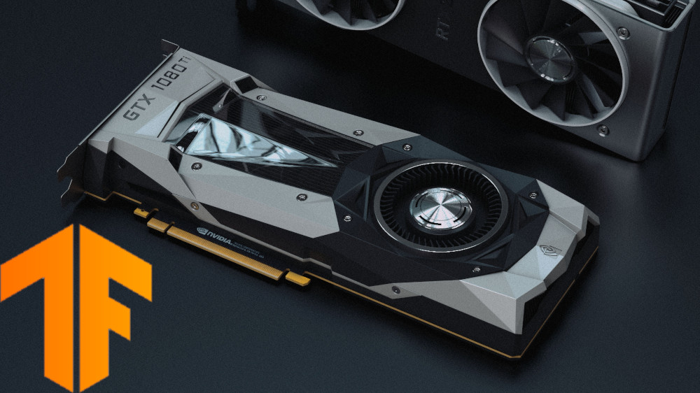
This tutorial will show you how to install TensorFlow with GPU support on Windows. You will need an NVIDIA graphics card that supports CUDA, as TensorFlow still only officially supports CUDA (see here: https://www.tensorflow.org/install/gpu).

If you are on Linux or macOS, you can likely install a pre-made Docker image with GPU-supported TensorFlow. This makes life much easier. See here for details (this article is about a year old, so a few things might be out of date). However, for those of us on Windows, we need to do things the hard way, as there is no NVIDIA Docker support on Windows.

See this article if you would like to install TensorFlow on Windows without GPU support.

[Update February 13, 2022] Updated some screenshots and a few commands to ensure that everything works with TensorFlow 2.7.0.

Prerequisites

To start, you need to play the version tracking game. First, make sure your graphics card can support CUDA by finding it on this list: https://developer.nvidia.com/cuda-gpus.

For example, my laptop has a GeForce GTX 1060, which supports CUDA and Compute Capability 6.1.

You can find the model of your graphics card by clicking in the Windows search bar and entering “dxdiag.” This tool will identify your system’s hardware. The Display tab should list your graphics card (if present on your computer).

DirectX Diagnostic Tool

Then, we need to work backwards, as TensorFlow usually does not support the latest CUDA version (note that if you compile TensorFlow from source, you can likely enable support for the latest CUDA, but we won’t do that here). Take a look at this chart to view the required versions of CUDA and cuDNN.

At the time of writing (updated Feb 13, 2022), this is the most recent TensorFlow version and required software:

Version Python version Compiler Build tools cuDNN CUDA
tensorflow_gpu-2.7.0 3.7-3.9 MSVC 2019 Bazel 3.7.2 8.1 11.2

Take a note of the particular required software versions listed for the particular TensorFlow version you wish to use. While you could compile TensorFlow from source to support newer versions, it’s much easier to install the specific versions listed here so we can install TensorFlow using pip.

Install Microsoft Visual C++ Compiler

The CUDA Toolkit uses the Microsoft Visual C++ (MSVC) compiler. The easiest way to install it is through Microsoft Visual Studio.

Download and install Visual Studio Community (which is free) from this site: https://visualstudio.microsoft.com/vs/community/. Yes, it’s a full IDE that we won’t use–we just need the compiler that comes with it.

[Update Feb 13, 2022] Note: at this time, the CUDA Toolkit installer will not find the latest version of Visual Studio Community (2022). You will need to install the older 2019 version by downloading from here.

Run the installer. You will be asked to install workloads. Click on the Individual components tab. Search for “msvc 2019” and select the latest MSVC C++ 2019 build tools version for your computer. For me, that was MSVC v142 – VS 2019 C++ x64/x86 build tools (Latest).

Install MSVC for Visual Studio Community

Click Install. When asked about continuing installation without a workload, click Continue. After installation is complete, you do not need to sign into Visual Studio. Simply close out all of the installation windows.

Install CUDA Toolkit

Navigate to the CUDA Toolkit site. Note the CUDA version in the table above, as it’s likely not the latest CUDA release. So, you’ll need to click on Archive of Previous CUDA Releases. Download the CUDA Toolkit version that is required for the TensorFlow version you wish to install (see the table in the Prerequisites section). For me, that would be CUDA Toolkit 10.1 update2 (Feb 13, 2022 update: CUDA Toolkit 11.2.2).

CUDA toolkit archive versions

Download the installer for your operating system (which is probably Windows 10). I used the exe (network) installer so that it downloads only the required components.

Run the installer. It will take a few minutes to scan your system. Once scanning is done, accept the license agreement and select Custom (Advanced) install.

Deselect the components you don’t need. For example, we likely won’t be developing custom CUDA kernels, so deselect Nsight Compute and Nsight Systems. I don’t have a 3D monitor, so I’ll deselect 3D Vision. I’ll keep PhysX selected for gaming, but feel free to deselect it, as it’s not needed by TensorFlow. You can leave everything else selected.

NVIDIA CUDA Toolkit installer

Click Next. Leave the installation directories as default (if you wish) and click Next again to download and install all of the drivers and toolkit. This will take a few minutes. Close the installer when it finishes.

Install cuDNN

GPU-accelerated TensorFlow relies on NVIDIA cuDNN, which is a collection of libraries used to run neural networks with CUDA.

Head to https://developer.nvidia.com/rdp/cudnn-download. Create an NVIDIA Developer account (or login if you already have one). Ignore the cuDNN version listed in the TensorFlow version table (in the Prerequisites section). Instead, head to the cuDNN Archive and download the version that corresponds to the CUDA version you just installed.

For example, I just installed CUDA 11.2, so I’m going to download cuDNN v8.2.1 (which is the latest version that supports CUDA 11.x). Choose the cuDNN Library for your operating system (e.g. Windows).

Download NVIDIA cuDNN library

The next part is a bizarre and seemingly old-fashioned method of installing a library. The full instructions can be found on this NVIDIA page (see section 3: Installing cuDNN on Windows).

Unzip the downloaded archive. Navigate into the unzipped directory and copy the following files into the CUDA installation directory (* being any files found with the listed file extension, and vxx.x is the CUDA version you installed).

Copy <cuDNN directory>\cuda\bin\*.dll to C:\Program Files\NVIDIA GPU Computing Toolkit\CUDA\vxx.x\bin

Install NVIDIA cuDNN dll files

Copy <cuDNN directory>\cuda\include\*.h to C:\Program Files\NVIDIA GPU Computing Toolkit\CUDA\vxx.x\include

Install NVIDIA cuDNN header files

Copy <cuDNN directory>\cuda\lib\x64\*.lib to C:\Program Files\NVIDIA GPU Computing Toolkit\CUDA\vxx.x\lib\x64

Install NVIDIA cuDNN lib files

Next, we need to update our environment variables. Open Control Panel > System and Security > System > Advanced System Settings.

Edit system properties in Windows

Click Environment Variables at the bottom of the window.

CUDA update environment variables

In the new window and in the System variables pane, select the Path variable and click Edit in the System variables pane.

You should see two CUDA entries already listed.

System path CUDA entries

If you do not see these listed, add the following directories to this Path list (where vxx.x is your CUDA version number):

  • C:\Program Files\NVIDIA GPU Computing Toolkit\CUDA\vxx.x\bin
  • C:\Program Files\NVIDIA GPU Computing Toolkit\CUDA\vxx.x\libnvvp

Click OK on the three pop-up windows to close out of the System Properties.

Install TensorFlow

You can install TensorFlow any way you wish, but I highly recommend doing so through Anaconda. It makes installing Python, various packages, and managing environments much easier.

Head to anaconda.com. Download the Individual Edition for your operating system (Windows x64). Anaconda comes pre-packaged with Python set at a particular version, so you will need to note the version of Python required by TensorFlow in the Prerequisites section. For me, I need something between 3.7-3.9. As a result, Python 3.9 that comes with Anaconda (at the time of this Feb 13, 2022 update) works fine.

Run the Anaconda installer, accepting all the defaults.

When it’s done, run the Anaconda Prompt (anaconda3).

The Anaconda Prompt

In the terminal, we’ll create a new Python environment, which will help us keep this version of TensorFlow separate from the non-GPU version. First, update conda with the following:

conda update -n base -c defaults conda

Then, enter the following commands to create a virtual environment:

conda create --name tensorflow-gpu
conda activate tensorflow-gpu

Install a version of Python supported by TensorFlow-GPU (as given by the table in the Prerequisites section) for your virtual environment (I’ll use Python version 3.9).

conda install python=3.9

Enter the following command to make sure that you are working with the version of Python you expect:

python --version

If you wish to also install Jupyter Notebook, you can do that with:

conda install jupyter

Rather than let pip try to figure out which version of TensorFlow you want (it will likely be wrong), I recommend finding the exact .whl file from TensorFlow’s site. Head to the TensorFlow Pip Installer page and look at the Package Location list.

Look under the Windows section for the wheel file installer that supports GPU and your version of Python. For me, this will be the wheel file listed with Python 3.9 GPU support. Note that GPU support (_gpu), TensorFlow version (-2.2.0), and supported Python version (-cp37) are listed in the filename. Highlight and copy the URL with the .whl file you want.

Download the correct TensorFlow wheel file

In Anaconda, enter the following command, replacing <wheel_url> with the URL that you copied in the previous step (i.e. paste it in).

python -m pip install <wheel_url>

Press ‘enter’ and let this run. It will take a few minutes.

Installing TensorFlow GPU wheel in Anaconda

When that’s done, go into the Python command line interface:

python

From there, enter the following commands (one at a time):

import tensorflow as tf 
print(tf.test.is_built_with_cuda()) 
print(tf.config.list_physical_devices('GPU'))

These will tell you if TensorFlow is capable of running on your graphics card. The first line imports TensorFlow, the second line makes sure it can work with CUDA (it should output “True”), and the third line should list the GPUs available to TensorFlow.

Test TensorFlow for GPU support in Python

Note that if you see any weird errors about missing Windows DLL files (whether in the Anaconda prompt, within Python, or in Jupyter Notebook), try the following from within Anaconda:

python -m pip install pypiwin32

Close the Anaconda prompt.

Running TensorFlow

When you’re ready to do some machine learning stuff, open the Anaconda Prompt and enter the following:

conda activate tensorflow-gpu

From there, you can use Python in Anaconda or start a Jupyter Notebook session (see here for a good overview of how to work with Jupyter Notebook):

jupyter notebook

If you wish to install a new Python package, like matplotlib, you can enter the following into the Anaconda Prompt (make sure you are in your environment, tensorflow-gpu, and exit Jupyter Notebook by pressing ctrl+c):

python -m pip install <name_of_package>

Alternatively, you can install a package from within Jupyter Notebook by running the following command in a cell:

!python -m pip install <name_of_package>

For example, here is how I installed matplotlib:

Install Python package from within Jupyter Notebook

Some libraries, like OpenCV, require you to install system components or dependencies outside of the Python environment, which means you can’t simply use pip. If so, check to see if the package is available in the conda-forge. If it is, you can install it in your Anaconda environment with:

conda install -c conda-forge <name_of_package>

Going Further

I hope this helps you get started using TensorFlow on your GPU! Thanks to Anaconda, you can install non-GPU TensorFlow in another environment and switch between them with the conda activate command. If the GPU version starts giving you problems, simply switch to the CPU version.

See the following videos if you are looking to get started with TensorFlow and TensorFlow Lite:

C++ on STM32

How to Use C++ with STM32CubeIDE

While C may be the preferred language of many embedded programmers, C++ does have a place, especially if you want to use certain libraries, like TensorFlow Lite for Microcontrollers. In this tutorial, I will show you how to get started making a program (blinky) for an STM32 microcontroller using C++ on STM32CubeIDE.

I will use an ST Nucleo-L432KC for this demonstration, as it’s small, fits on a breadboard, and still has a powerful ARM Cortex-M4 core. You are welcome to use any STM32 part, but I generally recommend starting out with one of the Nucleo boards.

Nucleo-L432KC

Plug your STM32 part into your computer.

Start STM32CubeIDE[link] and select File > New > STM32 Project. Select your target microcontroller or board (I’ll select my Nucleo-L432KC).

Select board in STM32CubeIDE

Click Next and then give your project a name. I like to prefix the board I’m using to the project name, so nucleo-l432-cpp-blinky is what I called mine. In Targeted Language, select C++.

Create new C++ project in STM32CubeIDE

Click Finish and click Yes when asked, “Initialize all peripherals with their default Mode?” Click Yes to open the new perspective.

Leave everything as default on the CubeMX device configuration GUI.

Leave all pin configurations to default

Code should be automatically generated. However, CubeMX generates a main.c file, which is not what we want for a C++ project. Right click on <project name> > Core > Src > main.c and select Rename. Change the name of the file to main.cpp. The compiler is sensitive to file suffixes, so .c files will compile as C code and .cpp or .cc files will compile as C++.

Rename main.c to main.cpp

Open the main.cpp file associated with the project. Scroll down to the while (1) loop and add the following  code just inside the while (1) loop:

HAL_GPIO_TogglePin(LD3_GPIO_Port, LD3_Pin);
HAL_Delay(500);

In context of the rest of the source code, this should look something like:

Where to place code in STM32CubeIDE generated template

Note that the GPIO port and pin names might be different for your board. If you’re using a Nucleo-64, the labels will be LD2_GPIO_Port and LD2_Pin.

In case you are wondering: yes, this is still C inside of a C++ file. Most of the STM32 HAL libraries are written in C, but they’re safe to call in C++.

Save and click Project > Build Project. You should notice that any .cpp or .cc files get automatically built with g++.

G++ compiler working on .cpp files

Click Run > Debug and click OK to accept the default launch configuration properties. Accept any prompts you might see to open the debug perspective. Click Run > Resume, and you should see the LED begin to blink.

Nucleo-L432KC blinky

That’s it! You should be ready to build your STM32 project in C++ with all of the object-oriented programming you so desire.

Please note that you can generally call C functions from within a C++ program and vice versa. You will need to add extern “C”  to your functions, which is detailed in this article.

If you are already working within a C project and you wish to convert it to C++, right-click on the project name in the project explorer pane and click Convert to C++. You will then need to rename any source files (to .cpp or .cc) you wish to be compiled by g++.

Convert project to C++ in STM32CubeIDE

If you right-click on any C++ project, you’ll find that you can revert it back to a C project using a similar method.

I hope this helps! I know that I’m looking forward to using C++ libraries in my STM32 project.

Using an ESP32 as a web server and using WebSockets to control hardware

How to Create a Web Server (with WebSockets) Using an ESP32 in Arduino
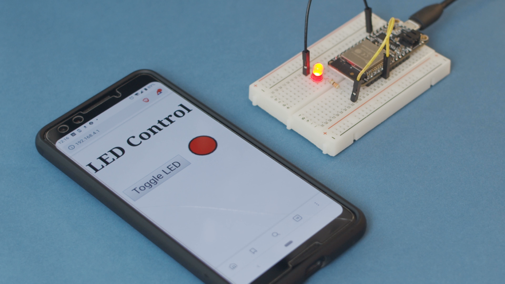
A few months ago, I created a video showing how to use WebSockets with an ESP32. WebSockets have proven to be very fast (relatively speaking) at controlling hardware over WiFi. They still rely on TCP, but they have little overhead, so the latency is much less than other methods (e.g. using separate web pages). However, I’ve had a few requests to show how to implement a web server on the ESP32. So, this tutorial will cover exactly that (but I’m still keeping WebSockets, because they’re cool).

If you like your tutorials in video format, here you go:


Overview

Rather than just host a simple web page, we’re going to build on the WebSocket idea. Let’s have our ESP32 be an access point (AP) and host a web page. When a browser requests that page, the ESP32 will serve it. As soon as the page loads, the client will immediately make a WebSocket connection back to the ESP32. That allows us to have fast control of our hardware connected to the ESP32.

ESP32 web server and WebSocket server diagram

The WebSocket connection is two-way. Whenever the page loads, it first inquires about the state of the LED from the ESP32. If the LED is on, the page will update a circle (fill in red) to reflect that. The circle on the page will be black if the LED is off. Then, whenever a user presses the “Toggle LED” button, the client will send a WebSocket packet to the ESP32, telling it to toggle the LED. This packet is followed by another request asking about the LED state so that the client can keep the browser updated with the state of the LED.

Hardware Hookup

Connect an LED to pin 15 of your ESP32 (don’t forget a limiting resistor! Something like 330Ω should work). Note that I’m using an Adafruit Feather HUZZAH32, so your pin numbering might be different.

Connecting LED to ESP32


Install SPIFFS Plugin

An ESP32 with an attached flash storage chip, like our HUZZAH32, can be configured to hold files, much like a mass storage device. However, it uses a very basic file system (there are no folders–files are just stored in a flat structure). This file system is known as the “Serial Peripheral Interface Flash File System” (SPIFFS). You can read more about SPIFFS here.

We need to use a special program to upload files over SPI. Head to https://github.com/me-no-dev/arduino-esp32fs-plugin and follow the instructions to install the Arduino plugin. Once done, restart Arduino, and you should see the option ESP32 Sketch Data Upload in the Tools menu.

ESP32 SPIFFS upload plugin in Arduino

Install Arduino Libraries

Make sure you have the ESP32 board definition installed for your particular board. If you’re using a board that’s supported by the Espressif Arduino board manager (such as the Adafruit HUZZAH32), you can follow the directions here.

Download the .zip files for the following libraries and install them in Arduino.

Arduino Code

Enter the following code into a new Arduino sketch. Take note of the SSID and password–we’ll need these to connect our phone/computer to the ESP32’s AP.

#include <WiFi.h>
#include <SPIFFS.h>
#include <ESPAsyncWebServer.h>
#include <WebSocketsServer.h>

// Constants
const char *ssid = "ESP32-AP";
const char *password =  "LetMeInPlz";
const char *msg_toggle_led = "toggleLED";
const char *msg_get_led = "getLEDState";
const int dns_port = 53;
const int http_port = 80;
const int ws_port = 1337;
const int led_pin = 15;

// Globals
AsyncWebServer server(80);
WebSocketsServer webSocket = WebSocketsServer(1337);
char msg_buf[10];
int led_state = 0;

/***********************************************************
 * Functions
 */

// Callback: receiving any WebSocket message
void onWebSocketEvent(uint8_t client_num,
                      WStype_t type,
                      uint8_t * payload,
                      size_t length) {

  // Figure out the type of WebSocket event
  switch(type) {

    // Client has disconnected
    case WStype_DISCONNECTED:
      Serial.printf("[%u] Disconnected!\n", client_num);
      break;

    // New client has connected
    case WStype_CONNECTED:
      {
        IPAddress ip = webSocket.remoteIP(client_num);
        Serial.printf("[%u] Connection from ", client_num);
        Serial.println(ip.toString());
      }
      break;

    // Handle text messages from client
    case WStype_TEXT:

      // Print out raw message
      Serial.printf("[%u] Received text: %s\n", client_num, payload);

      // Toggle LED
      if ( strcmp((char *)payload, "toggleLED") == 0 ) {
        led_state = led_state ? 0 : 1;
        Serial.printf("Toggling LED to %u\n", led_state);
        digitalWrite(led_pin, led_state);

      // Report the state of the LED
      } else if ( strcmp((char *)payload, "getLEDState") == 0 ) {
        sprintf(msg_buf, "%d", led_state);
        Serial.printf("Sending to [%u]: %s\n", client_num, msg_buf);
        webSocket.sendTXT(client_num, msg_buf);

      // Message not recognized
      } else {
        Serial.println("[%u] Message not recognized");
      }
      break;

    // For everything else: do nothing
    case WStype_BIN:
    case WStype_ERROR:
    case WStype_FRAGMENT_TEXT_START:
    case WStype_FRAGMENT_BIN_START:
    case WStype_FRAGMENT:
    case WStype_FRAGMENT_FIN:
    default:
      break;
  }
}

// Callback: send homepage
void onIndexRequest(AsyncWebServerRequest *request) {
  IPAddress remote_ip = request->client()->remoteIP();
  Serial.println("[" + remote_ip.toString() +
                  "] HTTP GET request of " + request->url());
  request->send(SPIFFS, "/index.html", "text/html");
}

// Callback: send style sheet
void onCSSRequest(AsyncWebServerRequest *request) {
  IPAddress remote_ip = request->client()->remoteIP();
  Serial.println("[" + remote_ip.toString() +
                  "] HTTP GET request of " + request->url());
  request->send(SPIFFS, "/style.css", "text/css");
}

// Callback: send 404 if requested file does not exist
void onPageNotFound(AsyncWebServerRequest *request) {
  IPAddress remote_ip = request->client()->remoteIP();
  Serial.println("[" + remote_ip.toString() +
                  "] HTTP GET request of " + request->url());
  request->send(404, "text/plain", "Not found");
}

/***********************************************************
 * Main
 */

void setup() {
  // Init LED and turn off
  pinMode(led_pin, OUTPUT);
  digitalWrite(led_pin, LOW);

  // Start Serial port
  Serial.begin(115200);

  // Make sure we can read the file system
  if( !SPIFFS.begin()){
    Serial.println("Error mounting SPIFFS");
    while(1);
  }

  // Start access point
  WiFi.softAP(ssid, password);

  // Print our IP address
  Serial.println();
  Serial.println("AP running");
  Serial.print("My IP address: ");
  Serial.println(WiFi.softAPIP());

  // On HTTP request for root, provide index.html file
  server.on("/", HTTP_GET, onIndexRequest);

  // On HTTP request for style sheet, provide style.css
  server.on("/style.css", HTTP_GET, onCSSRequest);

  // Handle requests for pages that do not exist
  server.onNotFound(onPageNotFound);

  // Start web server
  server.begin();

  // Start WebSocket server and assign callback
  webSocket.begin();
  webSocket.onEvent(onWebSocketEvent);
  
}

void loop() {
  
  // Look for and handle WebSocket data
  webSocket.loop();
}

Save your code (we’ll need the Arduino directory structure for SPIFFS in an upcoming step). I’ll give my program a name like “esp32_websocket_host.” Upload the program to your ESP32 and open a serial console with a baud rate of 115200. You should see the IP address of the ESP32 printed to the screen. When you run the Arduino soft access point software on the ESP32, the default IP address is 192.168.4.1.

ESP32 Access Point IP Address

Web Page Code

Let’s write a simple web page! Like most modern pages, it will contain a mixture of HTML and JavaScript. We leave out CSS, but you’re welcome to create your own .css file, if you wish to make the page look a little nicer. If you look back up in the Arduino code, you’ll see that we have a function to serve up a .css file. However, we will not be making a .css file for the sake of simplicity in this tutorial.

For SPIFFS to work, we need to put the files we wish to upload to the ESP32 in a folder named data/ inside the Arduino project directory:

esp32_websocket_host
 |_ esp32_websocket_host.ino
 |_ data
     |_ index.html

In Arduino, click Sketch > Show Sketch Folder to navigate to your project directory. Create a folder named data and create a new file named index.html inside that new folder. Open index.html with your favorite editor.

In index.html, paste the following code:

<!DOCTYPE html>
<meta charset="utf-8" />
<title>WebSocket Test</title>

<script language="javascript" type="text/javascript">

var url = "ws://192.168.4.1:1337/";
var output;
var button;
var canvas;
var context;

// This is called when the page finishes loading
function init() {

    // Assign page elements to variables
    button = document.getElementById("toggleButton");
    output = document.getElementById("output");
    canvas = document.getElementById("led");
    
    // Draw circle in canvas
    context = canvas.getContext("2d");
    context.arc(25, 25, 15, 0, Math.PI * 2, false);
    context.lineWidth = 3;
    context.strokeStyle = "black";
    context.stroke();
    context.fillStyle = "black";
    context.fill();
    
    // Connect to WebSocket server
    wsConnect(url);
}

// Call this to connect to the WebSocket server
function wsConnect(url) {
    
    // Connect to WebSocket server
    websocket = new WebSocket(url);
    
    // Assign callbacks
    websocket.onopen = function(evt) { onOpen(evt) };
    websocket.onclose = function(evt) { onClose(evt) };
    websocket.onmessage = function(evt) { onMessage(evt) };
    websocket.onerror = function(evt) { onError(evt) };
}

// Called when a WebSocket connection is established with the server
function onOpen(evt) {

    // Log connection state
    console.log("Connected");
    
    // Enable button
    button.disabled = false;
    
    // Get the current state of the LED
    doSend("getLEDState");
}

// Called when the WebSocket connection is closed
function onClose(evt) {

    // Log disconnection state
    console.log("Disconnected");
    
    // Disable button
    button.disabled = true;
    
    // Try to reconnect after a few seconds
    setTimeout(function() { wsConnect(url) }, 2000);
}

// Called when a message is received from the server
function onMessage(evt) {

    // Print out our received message
    console.log("Received: " + evt.data);
    
    // Update circle graphic with LED state
    switch(evt.data) {
        case "0":
            console.log("LED is off");
            context.fillStyle = "black";
            context.fill();
            break;
        case "1":
            console.log("LED is on");
            context.fillStyle = "red";
            context.fill();
            break;
        default:
            break;
    }
}

// Called when a WebSocket error occurs
function onError(evt) {
    console.log("ERROR: " + evt.data);
}

// Sends a message to the server (and prints it to the console)
function doSend(message) {
    console.log("Sending: " + message);
    websocket.send(message);
}

// Called whenever the HTML button is pressed
function onPress() {
    doSend("toggleLED");
    doSend("getLEDState");
}

// Call the init function as soon as the page loads
window.addEventListener("load", init, false);

</script>

<h2>LED Control</h2>

<table>
    <tr>
        <td><button id="toggleButton" onclick="onPress()" disabled>Toggle LED</button></td>
        <td><canvas id="led" width="50" height="50"></canvas></td>
    </tr>
</table>

Save this file. With your ESP32 plugged into your computer, open Arduino and click Tools > ESP32 Sketch Data Upload. Wait a moment, and all the files in the data/ folder (well, just the 1 file, index.html, for this example) should be uploaded to the ESP32.

Uploading files to the ESP32 using SPIFFS

Run It!

With the index.html file uploaded and the Arduino code running, you should be able to connect to the ESP32’s access point. Using your phone or computer, search for open WiFi access points and connect to the one named ESP32-AP. When asked for a password, enter LetMeInPlz (or whatever you set the AP password to in the Arduino code).

Since we are not running a captive portal, we will need to specifically browse to the IP address of the ESP32. Open a browser and enter 192.168.4.1 (or whatever you discovered the IP address of the ESP32 to be). You should be served the index.html page from the ESP32, which looks like a button and a circle. Zoom in, if needed (as we’re not doing any fancy formatting or CSS here).

Press the Toggle LED button, and you should see the LED connected to the ESP32 flicker to life. The circle on the page should also turn red to denote the state of the LED.

Using an ESP32 as a web server and using WebSockets to control hardware

Going Further

Feel free to use this as the basis for your next Internet-controlled hardware project. I suppose it fits in the category of “IoT,” and WebSockets can be super useful for controlling hardware with much less latency than many other methods. You can also use them to get fast updates, if you wish to create a custom dashboard showing sensor data.


How to Use printf on STM32

By default, most microcontrollers have no concept of a console, so you have to help them out a bit. When it comes to debugging, outputting information to some kind of console can be extremely useful. One option is to use semihosting with STM32CubeIDE.

However, semihosting can be extremely slow. Another good option is to output debug information over the serial port (UART). We can call the STM32 HAL functions (e.g. HAL_UART_Transmit), but sometimes it’s easier to use the standard C library functions printf, scanf, and so on. To do that, we need to re-write the underlying functions.

Note: the code for this section is taken from Carmine Noviello’s Mastering STM32 book. I am simply updating the process for how to get retargeting working in STM32CubeIDE. All credit goes to Carmine Noviello for his code. You are welcome to write your own retarget.h and retarget.c files, if you wish.

Start a new STM32 project with all the defaults. I am using a Nucleo-L476RG for this example. Enable UART, if needed. For almost all the Nucleo boards, UART2 is tied to the ST-LINK microcontroller, which gives us a virtual COM port over USB. Save and generate code.

The first thing we need to do is disable syscalls.c. This file defines many of the same functions that we are trying to make. If you do not disable it, you will likely get a “multiple definition” error when you try to compile and link. For example:

multiple definition of `_isatty'

Right-click on the syscalls.c file and select Properties. Under C/C++ Build > Settings, check Exclude resource from build.

Exclude files from STM32CubeIDE build

Click Apply and Close. The file name in the project browser should now be grayed out.

This will allow us to not include a file (or folder) when we compile and link in STM32CubeIDE. The process is similar for most other Eclipse-based IDEs.

Create a new file in the Inc directory called retarget.h. Copy the following code into this file:

// All credit to Carmine Noviello for this code
// https://github.com/cnoviello/mastering-stm32/blob/master/nucleo-f030R8/system/include/retarget/retarget.h

#ifndef _RETARGET_H__
#define _RETARGET_H__

#include "stm32l4xx_hal.h"
#include <sys/stat.h>

void RetargetInit(UART_HandleTypeDef *huart);
int _isatty(int fd);
int _write(int fd, char* ptr, int len);
int _close(int fd);
int _lseek(int fd, int ptr, int dir);
int _read(int fd, char* ptr, int len);
int _fstat(int fd, struct stat* st);

#endif //#ifndef _RETARGET_H__

Save this file.

Create a new file in the Src directory called retarget.c. Copy the following code into this file:

// All credit to Carmine Noviello for this code
// https://github.com/cnoviello/mastering-stm32/blob/master/nucleo-f030R8/system/src/retarget/retarget.c

#include <_ansi.h>
#include <_syslist.h>
#include <errno.h>
#include <sys/time.h>
#include <sys/times.h>
#include <limits.h>
#include <signal.h>
#include <../Inc/retarget.h>
#include <stdint.h>
#include <stdio.h>

#if !defined(OS_USE_SEMIHOSTING)

#define STDIN_FILENO  0
#define STDOUT_FILENO 1
#define STDERR_FILENO 2

UART_HandleTypeDef *gHuart;

void RetargetInit(UART_HandleTypeDef *huart) {
  gHuart = huart;

  /* Disable I/O buffering for STDOUT stream, so that
   * chars are sent out as soon as they are printed. */
  setvbuf(stdout, NULL, _IONBF, 0);
}

int _isatty(int fd) {
  if (fd >= STDIN_FILENO && fd <= STDERR_FILENO)
    return 1;

  errno = EBADF;
  return 0;
}

int _write(int fd, char* ptr, int len) {
  HAL_StatusTypeDef hstatus;

  if (fd == STDOUT_FILENO || fd == STDERR_FILENO) {
    hstatus = HAL_UART_Transmit(gHuart, (uint8_t *) ptr, len, HAL_MAX_DELAY);
    if (hstatus == HAL_OK)
      return len;
    else
      return EIO;
  }
  errno = EBADF;
  return -1;
}

int _close(int fd) {
  if (fd >= STDIN_FILENO && fd <= STDERR_FILENO)
    return 0;

  errno = EBADF;
  return -1;
}

int _lseek(int fd, int ptr, int dir) {
  (void) fd;
  (void) ptr;
  (void) dir;

  errno = EBADF;
  return -1;
}

int _read(int fd, char* ptr, int len) {
  HAL_StatusTypeDef hstatus;

  if (fd == STDIN_FILENO) {
    hstatus = HAL_UART_Receive(gHuart, (uint8_t *) ptr, 1, HAL_MAX_DELAY);
    if (hstatus == HAL_OK)
      return 1;
    else
      return EIO;
  }
  errno = EBADF;
  return -1;
}

int _fstat(int fd, struct stat* st) {
  if (fd >= STDIN_FILENO && fd <= STDERR_FILENO) {
    st->st_mode = S_IFCHR;
    return 0;
  }

  errno = EBADF;
  return 0;
}

#endif //#if !defined(OS_USE_SEMIHOSTING)

Save this file.

Your project directory structure should look like the following:

Adding files to STM32CubeIDE directory structureNotice that we’ve added retarget.h and retarget.c. We also removed syscalls.c from the build, but the file still exists in our project directory.

Include stdio.h and retarget.h in your main.c file. You can now use printf and scanf, as shown here:

/* Includes ------------------------------------------------------------------*/
#include "main.h"

/* Private includes ----------------------------------------------------------*/
/* USER CODE BEGIN Includes */
#include <stdio.h>
#include "retarget.h"
/* USER CODE END Includes */

/* Private typedef -----------------------------------------------------------*/
/* USER CODE BEGIN PTD */

/* USER CODE END PTD */

/* Private define ------------------------------------------------------------*/
/* USER CODE BEGIN PD */

/* USER CODE END PD */

/* Private macro -------------------------------------------------------------*/
/* USER CODE BEGIN PM */

/* USER CODE END PM */

/* Private variables ---------------------------------------------------------*/
UART_HandleTypeDef huart2;

/* USER CODE BEGIN PV */

/* USER CODE END PV */

/* Private function prototypes -----------------------------------------------*/
void SystemClock_Config(void);
static void MX_GPIO_Init(void);
static void MX_USART2_UART_Init(void);
/* USER CODE BEGIN PFP */

/* USER CODE END PFP */

/* Private user code ---------------------------------------------------------*/
/* USER CODE BEGIN 0 */

/* USER CODE END 0 */

/**
  * @brief  The application entry point.
  * @retval int
  */
int main(void)
{
  /* USER CODE BEGIN 1 */
  char buf[100];
  /* USER CODE END 1 */
  

  /* MCU Configuration--------------------------------------------------------*/

  /* Reset of all peripherals, Initializes the Flash interface and the Systick. */
  HAL_Init();

  /* USER CODE BEGIN Init */

  /* USER CODE END Init */

  /* Configure the system clock */
  SystemClock_Config();

  /* USER CODE BEGIN SysInit */

  /* USER CODE END SysInit */

  /* Initialize all configured peripherals */
  MX_GPIO_Init();
  MX_USART2_UART_Init();
  /* USER CODE BEGIN 2 */
  RetargetInit(&huart2);
  /* USER CODE END 2 */

  /* Infinite loop */
  /* USER CODE BEGIN WHILE */
  while (1)
  {
    printf("\r\nYour name: ");
    scanf("%s", buf);
    printf("\r\nHello, %s!\r\n", buf);
    /* USER CODE END WHILE */

    /* USER CODE BEGIN 3 */
  }
  /* USER CODE END 3 */
}

// ***REST OF INITIALIZATION CODE NOT SHOWN***

Build this project and open a debugging session in STM32CubeIDE. Open your favorite serial terminal program and connect to the Nucleo’s COM port (baud rate of 115200, 8-N-1). You should be greeted by a query. Type out some answer and press enter. Note that you will not be able to see what you typed. However, the program should append your entered text to a “Hello” message.

Using printf and scanf on STM32

Try not to overflow your assigned character buffer. Bad things happen if you do. Or you could write some kind of bounds checking in your code. Anyway, this is just a starting point to hopefully help you with debugging on your STM32 project.


Debugging STM32 with ST-LINK

How to Use Semihosting with STM32

Semihosting is a debugging tool that is built in to most ARM-based microcontrollers. It allows you to use input and output functions on a host computer that get forwarded to your microcontroller over a hardware debugging tool (e.g. ST-LINK). Specifically, it allows you to use printf() debugging to output strings to your IDE’s console while running code on the microcontroller. Note that we’ll be doing this over the Serial Wire Debug (SWD) port.

Before I show you how to enable semihosting with STM32CubeIDE, note that the downside of semihosting is that it is resource intensive and very slow. This post on the Embedded in Rust blog shows how printing a simple sentence over semihosting can take over 100 ms! The upside is every ARM controller should have semihosting available, which can be a lifesaver if that’s all you have.

If you need printf-style debugging (because you can’t or don’t want to do step-through debugging), here are your options on STM32 parts:

  • Semihosting: should be built in to every ARM chip, but slow
  • Serial (UART): fast, but you need extra pins and hardware (such as a USB to Serial converter board)
  • Virtual COM Port (VCP): fast, but you need USB hardware (see my previous post for setting this up)
  • Instrumentation Trace Macrocell (ITM): fast output over dedicated SWO pin, but it’s only available on Cortex-M3+ parts (i.e. Cortex-M0 chips don’t have it)

Nucleo

If you are using a Nucleo board, semihosting will work, but I highly recommend using Serial (UART) instead. It’s faster, and every Nucleo board has a built-in Serial to USB converter (it’s part of the ST-LINK chip already on the board). If you look at the schematic of your Nucleo board, you should see TX and RX lines going from the target chip to the ST-LINK chip (circled in red below).

UART lines on Nucleo-32 board

Hardware Hookup

For this demonstration, I’ll be using the STM32F070 Breakout Board that I put together (project files can be found here). You will also need an STMicroelectronics ST-LINK to use as a programmer and debugger:

Connect the following pins from the ST-LINK debugger to your STM32 part:

  • 3.3 V
  • SWCLK
  • GND
  • SWDIO
  • RST

Plug the ST-LINK into your computer.

CAUTION! Do not plug in the STM32 board (or give it separate power), as we are using the ST-LINK to power our target board. Otherwise, you might damage the target board.

Debugging STM32 with ST-LINK

Start a New Project

Create a new project for your STM32 part (select STM32F070CB if you’re using the breakout board I mentioned earlier). You can leave everything in the graphical CubeMX portion as default.

STM32CubeIDE

Save and generate code.

Set Linker Parameters

Before writing any code, we need to tell our linker to use the newlib-nano libraries, which houses things like our printf() function. As a result, we also need to tell the linker to ignore the default syscalls.c file. If you forget this step, you will likely end up with several errors like: multiple definition of `_isatty’

To start, go to Project > Properties.

Go in to C/C++ General > Paths and Symbols. Click on the Source Location tab. Click on the arrow next to /<your project>/Src to view the filter. Select Filter (empty) and click the Edit Filter… button. Add syscalls.c to the Exclusion patterns list and click OK.

Adding syscalls.c to the exclusion list

Click Apply.

On the left-side pane, go into C/C++ Build and select the Tool Settings tab. Then, select MCU GCC Linker > Libraries. In the libraries pane, click the Add… button and enter rdimon. This enables librdimon for us to make system calls with semihosting.

Enable librdimon in STM32CubeIDE

Next, click on MCU GCC Linker > Miscellaneous while still in the Tool Settings tab. Click the Add… button and enter –specs=rdimon.specs into the dialog box.

Adding specs to linker

If you have used another STM32 IDE before and got semihosting to work, you probably needed to specify nano.specs and nosys.specs in the linker options. If you take a look at MCU Settings and MCU GCC Linker > General (within the Tool Settings tab), you will see that both of these have been set by default in STM32CubeIDE.

Click Apply and Close.

Add printf Code

Open Src/main.c. Above int main(void) , add the following line (I put mine in the USER CODE 0 section):

extern void initialise_monitor_handles(void);

In int main(void)  (before the while(1) loop), add the following line (I put mine in the USER CODE 1 section):

initialise_monitor_handles();

This configures the semihosting system calls for us.

Finally, inside the while(1) loop, add the following:

printf("Hello, World!\n");
HAL_Delay(1000);

To summarize, here is the section of code from main.c that you need to worry about:

/* Private user code ---------------------------------------------------------*/
/* USER CODE BEGIN 0 */
extern void initialise_monitor_handles(void);
/* USER CODE END 0 */

/**
* @brief The application entry point.
* @retval int
*/
int main(void)
{
/* USER CODE BEGIN 1 */
initialise_monitor_handles();
/* USER CODE END 1 */

/* MCU Configuration--------------------------------------------------------*/

/* Reset of all peripherals, Initializes the Flash interface and the Systick. */
HAL_Init();

/* USER CODE BEGIN Init */

/* USER CODE END Init */

/* Configure the system clock */
SystemClock_Config();

/* USER CODE BEGIN SysInit */

/* USER CODE END SysInit */

/* Initialize all configured peripherals */
/* USER CODE BEGIN 2 */

/* USER CODE END 2 */

/* Infinite loop */
/* USER CODE BEGIN WHILE */
while (1)
{
/* USER CODE END WHILE */

/* USER CODE BEGIN 3 */
printf("Hello, World!\n");
HAL_Delay(1000);
}
/* USER CODE END 3 */
}

Click Project > Build Project to compile and link everything.

Set Debug Configuration

Select Run > Debug As > STM32 MCU C/C++ Application. You should get a pop-up window asking you to “edit launch configuration properties.” If you have already done this once before, you will not get the launch configuration window. To get it, click on Run > Debug Configurations and select <your project>.elf under STM32 MCU Debugging.

Click on the Debugger tab. Change the Debug probe to ST-LINK (OpenOCD).

If you are using an official ST-LINK, you should be good to go. However, note that RST pin of the knockoff ST-LINK boards (such as the ST-LINK/V2 I listed above) may not work. As a result, you will need to use the software reset option when GDB starts.

To enable software reset, click Show generator options… in the Debugger tab (while still in the Debug Configurations window). Under Mode Setup, change Reset Mode to Software system reset.

Change OpenOCD to software reset in STM32CubeIDE

Go to the Startup tab and enter the following command: monitor arm semihosting enable

Enable semihosting session in gdb

This tells the GDB session to allow for semihosting. Click OK, and switch to the debugging perspective when asked.

Run It

In the debugging perspective, click Run > Resume, and you should see “Hello, World!” being printed at the bottom of the console once per second.

printf with semihosting on STM32CubeIDE

Semihosting can help you with your debugging efforts, should you need some kind of console output. Note that other standard commands, like scanf, should work (I have not tested it yet).

Nucleo-32 connected to a USB for VCP

Getting Started with STM32 Nucleo USB (Virtual Com Port)

As I continue my journey with STM32 development, I wanted to share my findings with how to get a Virtual COM Port (VCP) working with a Nucleo board.

Specifically, I’m using the Nucleo-F042K6, as it has a built-in USB device peripheral (full speed), and it does not require an external crystal. I highly recommend looking over the USB Hardware and PCB Guidelines document from ST Microelectronics to learn about what’s needed for your particular STM32 part. Note that if you are using a Nucleo board with an STM32F401 or STM32F411, you will need to solder an external crystal to the board, as it is unpopulated on those boards.

To begin, strip a USB cable or get a USB breakout board (like this one from SparkFun) and connect the lines to a breadboard as shown in the Fritzing diagram below. Make the following connections:

  • VUSB → Diode → Nucleo 5V (don’t want to short something if we’re plugging in 2 USB cables!)
  • USB D- → Nucleo D10 (PA11)
  • USB D+ → Nucleo D2 (PA12)
  • USB GND → Nucleo GND
  • USB GND → USB Shield (don’t know if this is necessary, but it makes me feel better)

Also, this is super important: remove the jumper that comes default on your Nucleo board! It bridges D2 and GND and will short out our D+ line if left in place.

Connecting an STM32 Nucleo board to USB for VCP

Plug the two USB cables from the Nucleo board into your computer. We’ll be sending our compiled program over to the ST-LINK side of the board, and the VCP will enumerate on the USB lines that we just added. I don’t have a bootloader working (yet) to where we can send binary files over VCP, but that’s on my to-do list.

Nucleo-32 connected to a USB for VCP

For this, I’m using STM32CubeIDE along with the STM32F0 HAL API.

In STM32CubeIDE, start a new project (File > New > STM32 Project). Choose your part or board. I’ll pick the Nucleo-F042K6, since that’s the board I have.

STM32CubeIDE part selector

On the next screen, give your project a useful name (such as “nucleo-f042k6-vcp-test”). Leave everything else as default. We’ll be using C as our language for this example. Click Finish, and you’ll be asked a few questions:

  • Yes to “initialize all peripherals with their default Mode”
  • Yes to “open this perspective now”

In the CubeMX configuration perspective, you’ll need to enable a few options to initialize the USB as a Virtual COM Port. In the Pinout & Configuration tab, go to Categories > Connectivity and click USB. Enable Device (FS). You should see PA11 and PA12 be automatically configured for USB_DM and USB_DP.

STM32CubeIDE selecting USB

Under Categories > Middleware, select USB_DEVICE. Change Class For FS IP to Communication Device Class (CDC). This tells the USB stack that we want to enumerate as a CDC device, which will allow us to send serial data to and from our computer across the USB lines.

Select USB CDC

Click on the Clock Configuration tab. The software will tell you that your clocks have issues. By default, the Nucleo-F042K6 board is configured for 8 MHz clocks for almost everything. We need to bump those up to 48 MHz for USB to work. Luckily, you can just click Yes on the pop-up when asked to run the automatic clock issues solver. This should automatically change all of the necessary clocks to 48 MHz.

Updating clock speeds to match USB

In the Project Manager tab, change the Minimum Heap Size to 0x100. The STM32F042K6 comes with 6 kB of RAM, which isn’t a whole lot. USB functionality takes up probably 2-3 kB worth of that memory, so we need to be careful about how we use the rest.

We can free up some space by adjusting the minimum heap and stack sizes. These parameters essentially reserve sections of data memory for the heap and stack. By setting 0x200 and 0x400, we’ve told the processor to reserve 1 kB of RAM for the heap and stack, respectively. We need to lower one of them in order to accommodate the USB functions. I chose heap, as it seems less likely we’ll be using dynamically allocated memory for this application.

If you get an error message like `._user_heap_stack’ will not fit in region `RAM’  or region `RAM’ overflowed by 64 bytes  when you compile, it means you are running out of RAM in your application. You will need to go into the Device Configuration Tool (the .ioc file) and adjust the stack and heap settings as described above. Alternatively, you can go into the .ld linker script and look for the _Min_Heap_Size  and _Min_Stack_Size  settings there (just know that this file will be overwritten if you make changes in the graphical Device Configuration Tool).

Allocate minimum heap size in STM32CubeIDE

Click File > Save to save the changes to the CubeMX configuration. You’ll be asked if you want to generate Code. Click Yes.

In your project files, navigate to the Src directory. Notice that you have several USB-related files that have been added. usbd_cdc_if.c contains the functions that allow us to send and receive serial data using the USB Communication Device Class. Feel free to peek in there, if you wish.

Open up Src > main.c. At the top, under /* USER CODE BEGIN Includes */ , enter the following line:

#include "usbd_cdc_if.h"

This will let us call functions from the CDC library. Scroll down to our while(1) loop in main. Under /* USER CODE BEGIN 3 */  (but still inside the while loop), enter the following:

uint8_t buffer[] = "Hello, World!\r\n";
CDC_Transmit_FS(buffer, sizeof(buffer));
HAL_Delay(1000);

Here, we create a simple string and call a USB CDC function to send out that string over the USB lines. We then wait for 1 second before repeating this action ad infinitum.

Code to transmit a string over a serial VCP via USB CDC in STM32

Click Project > Build All to build the project. Click Run > Debug As > STM32 MCU C/C++ Application. A pop-up window will appear asking you to create a new launch configuration. Note that if you are not using a Nucleo board or an ST-LINK, you can change the hardware debugger (e.g. to a Segger J-LINK) in the Debugger tab. If you are using a Nucleo, leave everything as default and click OK.

New STM32 debug configuration

If asked to switch to the Debug perspective, click Switch. When the new perspective opens, click Run > Resume (or the play button on the toolbar).

Debugging in STM32CubeIDE

Your code should now be running, and the microcontroller will enumerate as a USB device! Feel free to verify the new serial port in your OS’s device manager. This should show up as a USB serial or COM port.

STM32 as a USB serial (COM) port

Open your favorite serial terminal program, and enter the following connection details:

  • Port: USB serial or COM port discovered above
  • Baud rate: 9600
  • Data bits: 8 (default)
  • Parity: None (default)
  • Stop bits: 1 (default)

Setting serial terminal to listen for STM32

Open the serial connection, and you should be greeted by that oh-so-familiar phrase, repeating over and over again:

STM32 outputting strings via serial COM port on USB

When you’ve had enough strings, feel free to press the stop button in the IDE to stop the program from running on the STM32.

Interestingly enough, the STM32 seems to support autobaud detection by default. Try changing the serial terminal’s baudrate to anything else and see if you can still receive text. I bet that disabling autobaud would save some RAM, but I have not discovered how yet.

From what I understand, CDC_Receive_FS() is a callback, so you’ll need to change its definition in usbd_cdc_if.c to get it to work. I haven’t played with it yet, so that’ll be a post for another time.

I hope that this helps you get started with your STM32 USB journey!


KiCad tutorial worksheet PCB

KiCad Tutorial – Beginner Worksheet

Download worksheet here: KiCad Tutorial Worksheet

Please note that the worksheet is licensed under CC BY 4.0.

If you would like to teach yourself KiCad, please download the above worksheet and get started! You are also welcome to download it to teach a workshop at your school, makerspace, Maker Faire, etc.

About the KiCon Beginner Workshop

The first ever KiCad Conference was a success by any measure. The event was sold out, the talks were top-notch, and the attendees were every bit as friendly as they were geeky tinkerers.

As part of that conference, I pledged my time to help run a beginner workshop. We had at least a dozen folks show up just starting out with the EDA software or looking for a refresher. To help them out, I put together a worksheet, which allowed attendees to come in and out of the room as they desired so they could attend other talks.

You are more than welcome to download the worksheet to teach yourself KiCad at your own pace, learn how to make a single-sided PCB, and mill or fabricate it if you so desire!

Be aware that the worksheet was written for KiCad 5.1.0. If you have a different version, some of the instructions might be a little off. During the workshop, we found that individuals with KiCad 5.0.x lacked the footprint for the switch, which was apparently added in the default KiCad library during the 5.1.0 update.

If you need the 5.1.0 switch footprint library, it can be found here. Note that the library has been renamed so as to avoid naming conflicts within KiCad.

Making the Board

The workshop was designed to allow folks to finish designing a full PCB on site, have it milled in the afternoon, and walk away with a full, blinking LED pin by the evening.

You are also welcome to create your own PCB based on the blinky design. If you have access to a CNC milling machine, such as the Bantam Tools desktop PCB milling machine, you can mill your own board at home. These videos might give you a good starting point to home PCB milling.

Alternatively, you could have a fabrication shop, like OSH Park, make the boards for you.

I recommend referring to this bill of materials (BOM) to figure out which components you need to buy to finish assembling your pin.

Resources

  • github.com/ShawnHymel/kicon19-blinky – GitHub repository with almost all of the files you should need
  • Worksheet – Step-by-step guide for creating a single-sided PCB with KiCad
  • BOM – Components needed to assembly the board (some soldering required)
  • Intro to KiCad Videos – My videos for DigiKey that dive into more KiCad details (note: based on KiCad 4).


SAMD21 PWM with the FDPLL

Arduino Zero (SAMD21) FDPLL with CMSIS

One of the coolest, tucked-away features in the SAMD21 is the fractional digital phase locked loop (FDPLL). I still only have a vague idea of how phase locked loops (PLLs) work, but nonetheless, we can use the SAMD21’s PLL to create a 96 MHz clock.

The bad news is that, to the best of my knowledge, you cannot use this clock signal as the main clock source for the SAMD21 (essentially overclocking it). However, we can use it to power some other peripherals, like the generic clocks, timers, and pulse width modulation (PWM) signals.

If you are not familiar with how the clocks on the SAMD21 work, I recommend reading my previous post. You will also need to refer to the SAMD21 datasheet.

Let’s take a look at how you use the FDPLL on the SAMD21.

Step 1: Select a Clock Source

The FDPLL isn’t a standalone clock. You’ll need to select a source to feed the PLL, and the source clock needs to be in the 32 kHz to 2 MHz range. According to section 16.8.19 (page 208) of the datasheet, there are only 3 acceptable clock sources for the FDPLL: XOSC32, XOSC, and a specific GCLK (known as GCLK_DPLL). You can set the clock source for the PLL in the DPLLCTRLB register.

Clock sources for DPLL on SAMD21

Step 2: Configure FDPLL

Next, you will need to set the frequency multiplier in DPLLRATIO register. There are two numbers you must configure: the ratio (LDR bits) and the ratio fractional part (LDRFRAC bits). The equation below (from section 16.6.8.3, page 158) shows how to calculate the output frequency of the FDPLL. fclk_fdpll96m is the output frequency and fclk_fdpll96m_ref is the reference clock (the input clock source).

SAMD21 FDPLL equation

So, if we want to turn a 1 MHz clock source into a 96 MHz output, we would set LDR to 95 and LDRFRAC to 0.

Step 3: Turn It On

By default, the FDPLL is disabled on reset. To enable it, we just write a 1 to the ENABLE bit in the DPLLCTRLA register.

Step 4: Use It!

The FDPLL can be used as a clock source for any of the generic clocks found in the generic clock controller. This includes the USB clock, watchdog timer, clock channels, SERCOMs, etc. Section 14.8.3 (page 107) has a table (too big to copy here) that gives you an idea of the available GCLKs. If you use one of the GCLK channels, you can use it to clock a peripheral, like PWM!

Example: A More Complicated 1 MHz Signal

In my last post, I showed you how to create a 1 MHz signal using GCLK4, TCC2, and a PWM peripheral. Let’s do the same thing, but in a much more roundabout way!

We’ll feed GCLK4 from the main 48 MHz clock, divide the clock by 48, feed that signal to GCLK_DPLL, which is then sent to the FDPLL. The DPLL will create a 96 MHz clock signal, which we’ll send to GCLK5 to be used as the basis for TCC2 and our PWM signal. This diagram should offer a much better explanation of what’s going on:

SAMD21 PWM with the FDPLL

Because our PWM clock is running twice as fast as in the previous example, we’ll need to adjust the TOP to be twice as high. We’ll use 95 instead of 47 to achieve our 1 MHz signal.

Here is the Arduino code to accomplish this:

// I have no idea why these definitions were left out of the Arduino headers
#define GCLK_GENCTRL_SRC_DPLL96M_Val 0x8ul  // (GCLK_GENCTRL) DPLL96M output
#define GCLK_GENCTRL_SRC_DPLL96M (GCLK_GENCTRL_SRC_DPLL96M_Val << \
                                  GCLK_GENCTRL_SRC_Pos)

// Number to count to with PWM (TOP value). Frequency can be calculated by
// freq = GCLK4_freq / (TCC2_prescaler * (1 + TOP_value))
// With TOP of 95, we get a 1 MHz square wave in this example.
// TCC2 is 16 bits
uint16_t period = 96 - 1;
 
void setup() {

  // Flash wait states NVMCTRL->CTRLB.bit.RWS set to 1 by Arduino framework

  // Configure generic clock generator 4
  GCLK->GENCTRL.reg = GCLK_GENCTRL_IDC |          // Improve duty cycle
                      GCLK_GENCTRL_GENEN |        // Enable generic clock gen
                      GCLK_GENCTRL_SRC_DFLL48M |  // Select 48MHz as source
                      GCLK_GENCTRL_ID(4);         // Apply to GCLK4
  while (GCLK->STATUS.bit.SYNCBUSY);              // Wait for synchronization

  // Set clock divider of 48 to generic clock generator 4 (1 MHz)
  GCLK->GENDIV.reg = GCLK_GENDIV_DIV(48) |        // Divide 48 MHz by 48
                     GCLK_GENDIV_ID(4);           // Apply to GCLK4 4
  while (GCLK->STATUS.bit.SYNCBUSY);              // Wait for synchronization

  // Enable GCLK4 and connect it to GCLK_DPLL
  GCLK->CLKCTRL.reg = GCLK_CLKCTRL_CLKEN |        // Enable generic clock
                      GCLK_CLKCTRL_GEN_GCLK4 |    // Select GCLK4
                      GCLK_CLKCTRL_ID(1);         // Feed GCLK4 to GCLK_DPLL
  while (GCLK->STATUS.bit.SYNCBUSY);              // Wait for synchronization

  // Set DPLL ratio to 1 MHz * (95 + 1) = 96 MHz
  SYSCTRL->DPLLRATIO.reg = SYSCTRL_DPLLRATIO_LDRFRAC(0) | // Ratio fractional
                           SYSCTRL_DPLLRATIO_LDR(95);     // Ratio

  // Configure DPLL to disregard phase lock and select GCLK as source
  SYSCTRL->DPLLCTRLB.reg = SYSCTRL_DPLLCTRLB_LBYPASS |    // Bypass lock
                           SYSCTRL_DPLLCTRLB_WUF |        // Wake up fast
    SYSCTRL_DPLLCTRLB_REFCLK(SYSCTRL_DPLLCTRLB_REFCLK_GCLK_Val); // Select GCLK
  
  // Enable DPLL
  SYSCTRL->DPLLCTRLA.reg |= SYSCTRL_DPLLCTRLA_ENABLE;
  
  // Configure generic clock generator 5
  GCLK->GENCTRL.reg = GCLK_GENCTRL_IDC |          // Improve duty cycle
                      GCLK_GENCTRL_GENEN |        // Enable generic clock gen
                      GCLK_GENCTRL_SRC_DPLL96M |  // Select DPLL as source
                      GCLK_GENCTRL_ID(5);         // Apply to GCLK5
  while (GCLK->STATUS.bit.SYNCBUSY);              // Wait for synchronization

  // Set clock divider of 1 to generic clock generator 5 (96 MHz)
  GCLK->GENDIV.reg = GCLK_GENDIV_DIV(1) |        // Divide 96 MHz by 1
                     GCLK_GENDIV_ID(5);           // Apply to GCLK5
  while (GCLK->STATUS.bit.SYNCBUSY);              // Wait for synchronization

  // Enable GCLK5 and connect it to TCC2 and TC3
  GCLK->CLKCTRL.reg = GCLK_CLKCTRL_CLKEN |        // Enable generic clock
                      GCLK_CLKCTRL_GEN_GCLK5 |    // Select GCLK5
                      GCLK_CLKCTRL_ID_TCC2_TC3;   // Feed GCLK5 to TCC2/TC3
  while (GCLK->STATUS.bit.SYNCBUSY);              // Wait for synchronization
  
  // Divide counter by 1 giving 96 MHz (10.42 ns) on each TCC2 tick
  TCC2->CTRLA.reg |= TCC_CTRLA_PRESCALER(TCC_CTRLA_PRESCALER_DIV1_Val);

  // Use "Normal PWM" (single-slope PWM): count up to PER, match on CC[n]
  TCC2->WAVE.reg = TCC_WAVE_WAVEGEN_NPWM;         // Select NPWM as waveform
  while (TCC2->SYNCBUSY.bit.WAVE);                // Wait for synchronization

  // Set the period (the number to count to (TOP) before resetting timer)
  TCC2->PER.reg = period;
  while (TCC2->SYNCBUSY.bit.PER);

  // Set PWM signal to output 50% duty cycle
  // n for CC[n] is determined by n = x % 4 where x is from WO[x]
  TCC2->CC[0].reg = period / 2;
  while (TCC2->SYNCBUSY.bit.CC0);

  // Configure PA16 (D11 on Arduino Zero) to be output
  PORT->Group[PORTA].DIRSET.reg = PORT_PA16;      // Set pin as output
  PORT->Group[PORTA].OUTCLR.reg = PORT_PA16;      // Set pin to low

  // Enable the port multiplexer for PA16
  PORT->Group[PORTA].PINCFG[16].reg |= PORT_PINCFG_PMUXEN;

  // Connect TCC2 timer to PA16. Function E is TCC2/WO[0] for PA16.
  // n for PMUX[n] is given by floor(pin_num / 2)
  // Odd pin num (2*n + 1): use PMUXO
  // Even pin num (2*n): use PMUXE
  PORT->Group[PORTA].PMUX[8].reg = PORT_PMUX_PMUXE_E;

  // Enable output (start PWM)
  TCC2->CTRLA.reg |= TCC_CTRLA_ENABLE;
  while (TCC2->SYNCBUSY.bit.ENABLE);              // Wait for synchronization
}

void loop() {
  // Do nothing
}

This is certainly a crazy, circuitous route to take for a 1 MHz signal, but it offers much greater control of the PWM frequency. If your application needs this kind of control (e.g. motor controls), firing up the PLL could be incredibly helpful.

In case you’re wondering where I’m going with this project: let’s just say that this fine control of clock speeds lets us create something like a digitally controlled oscillator (DCO).

1 Mhz square wave on Analog Discovery 2

Arduino Zero (SAMD21) Raw PWM Using CMSIS

Arduino has a habit of making pulse width modulation (PWM) pins with a set frequency (or limited frequency options). For the average user, this is not a bad thing, considering it hides all the ugliness (or beauty, depending on your perspective) of manually setting registers.

For those of us that want to dig deeper into the SAMD21, there are a few options. Almost all modern implementations of the ARM Cortex architectures can use the Cortex Microcontroller Software Interface Standard (CMSIS). This is a set of firmware libraries that provide an interface to the registers along with some other functions. Ideally, you should be able to use CMSIS regardless of the manufacturer of the chip (e.g. Microchip, STMicroelectronics, TI).

Some vendors have decided to include their own abstraction layer on top of CMSIS to help people configure and use their parts. In some cases, this can make setting up registers easy (especially if there is a slick GUI program that generates code for you, like STMicro’s STM32CubeMX). Microchip’s abstraction layer is known as the Advanced Software Framework (ASF).

Many professional developers swear by the vendor-provided abstraction layer (e.g. ASF). If you’re like me, you want to know what’s going on at the register level. Not that there is anything wrong with ASF, I just like to learn about the low-level stuff.

Here’s the problem: when it comes to manually configuring registers for 32-bit ARM microcontrollers, it’s vastly more difficult than it is for most other 8- or 16-bit architectures.

I’ve spent the last few days digging through the SAMD21 datasheet and online examples to get some insight into using CMSIS. On the surface, it’s not too bad: you just need to set some values in some registers to get a pin to output a square wave. In reality, it requires a good amount of code to perform this simple action.

Please note that I am just beginning to understand how the SAMD21 works, and this article is simply a chronicle of my learning journey. If you think I missed something or got something wrong, please let me know in the comments!

The best description I can find for how this works is from section 14.3 (page 95) in the datasheet:

To configure a pin for PWM requires a good bit of effort. The basic idea is to select a clock source from SYSCTRL (such as the 48 MHz system clock) and connect it to a Generic Clock Generator. The SAMD21 has 9 different generators we can use. We can configure each generator to have its own divider and mask (so that we can run various peripherals off different speeds thanks to having separate clock generators).

Then, we connect our generator to the peripheral we want. In the example below, we’ll be using the Timer/Counter for Control Applications (TCC). The SAMD21 also has a Timer/Counter peripheral (TC), but from what I could grasp, it’s “TCC lite” (i.e. TCC with less features).

Once we have our peripheral configured (TCC, in this case), we then want to connect that to a hardware pin so that we get an actual waveform to appear.

While this might seem extremely complicated, the upside is that the SAMD21 is an extremely powerful chip. We can connect and configure different peripherals in many, many different ways (thanks to all this multiplexing of clock signals!).

Let’s walk through an example of outputting a 1 MHz square wave on pin PA18. Note that PA18 is D10 on the Arduino Zero, Adafruit Feather M0, and the SparkFun SAMD21 Mini Breakout board. If you don’t have one of these boards, check your schematic to see where PA18 goes. Also, note that there are lots of ways to output a 1 MHz square wave on a pin. We’ll be doing this using a 50% duty cycle PWM and the 48 MHz system clock.

Step 1: Enable Clock Source in SYSCTRL

You have a few options for clock sources:

  • External oscillator (0.4 – 32 MHz)
  • External oscillator at 32 kHz
  • Internal oscillator at 32 kHz
  • Ultra low power internal oscillator at 32 kHz
  • Internal oscillator at 8 MHz
  • Digital frequency-locked loop at 48 MHz
  • Fractional digital phase-locked loop (48 – 96 MHz)

Some of these, like the phase-locked loop, can only be used to provide a clock signal for the peripherals. It cannot be used as a system clock. As such, the maximum processing speed of the SAMD21 is 48 MHz.

In most of the Arduino implementations of the SAMD21, the 48 MHz clock is already enabled for us (in the background, as part of the framework). That means we don’t need to initialize it our user code.

Step 2: Configure Clock Generator and Connect It to a Clock Source

Generic clock generators create a square wave (inside the chip) that we can frequency divide, mask, and connect to peripherals. The SAMD21 has 9 clock generators for us to use. We need to pick one, initialize it, and connect it to our clock source.

From what I could find, Generic Clock Generators 0 and 1 were used for other Arduino functions, so you probably want to avoid using those.

Step 3: Configure Peripheral and Connect It to a Clock Generator

The SAMD21 has several peripherals for us to use. We’ll be focusing on the TCC for this example. There are 3 TCCs for us to use, and each one has its own set of unique features. TCC0 and 1 are 24 bits wide whereas TCC2 is limited to 16 bits for its counter. From section 30.1 (page 651) in the datasheet:

SAMD21 TCC configuration chart

With TCC, we can set it to generate a PWM waveform on a pin. We will use a simple, single-slope PWM wave that counts up to a given value. During that counting process, if the value of the counter is equal to the Compare and Capture (CC) register, then the pin will toggle to low. Once the counter reaches the value in the Period (PER) register, then the pin will toggle back to high. The counter resets and starts over again.

From section 30.6.2.5 (page 660) in the datasheet, we get a diagram of how the PWM counter works. Note that TOP, for this mode, refers to the value in the PER register.

SAMD21 Normal PWM operation

WO[x] stands for “waveform output,” and the x is the pin we wish to use. In the datasheet, navigate to section 6.1 (page 21) to see a chart of the pin to function mapping (too long to copy here). Under functions E and F, you’ll see the TCC options. For our PA18 example, you can see that function F is TCC0/WO[2].

Here is the really confusing part: there are only 4 CC options (CC0 through CC3) for setting the duty cycle, but the pin/function mapping chart shows up to WO[7] channels. So, how do we connect a given CC register to a WO pin that’s greater than 3? This poorly labeled chart buried away in part 30.6.3.7 (page 678) holds the key:

SAMD21 output matrix

WO[7] is on the left and WO[0] is on the right. The OTMX configuration bits are found in the WEXCTRL register. By setting the OTMX bits to values 0-3, you can change which CC registers the various WO pins use.

By default, OTMX is set to 0x0, so the top row of the chart is used. Since we are using WO[2], we need to use CC2, according to the chart. If you want to use WO[5], you would use CC1.

Step 4: Set Data Direction and Peripheral for Pin

Because we’ve already configured TCC0/WO[2], that locks us in to pin PA18. Pins have a variety of functions that they can be set to (once again, refer to the chart in section 6.1).  For our project, we need to set PA18 to Function F (TCC0/WO[2]). We also need to set PA18 as an output in the data direction (DIR) register.

Example Code

Now for the moment you’ve all been waiting for (or, let’s be honest, the part you scrolled down for, skipping the above descriptions). Here is some example Arduino code to create a 1 MHz square wave on PA18 (D10 on the Zero, Adafruit Feather M0, or SparkFun SAMD21 Mini).

Note: Many thanks to MartinL on the Arduino forums! Their code snippet (found here) helped me tremendously. The following code is based on that snippet.

// Number to count to with PWM (TOP value). Frequency can be calculated by
// freq = GCLK4_freq / (TCC0_prescaler * (1 + TOP_value))
// With TOP of 47, we get a 1 MHz square wave in this example
uint32_t period = 48 - 1;
 
void setup() {

  // Because we are using TCC0, limit period to 24 bits
  period = ( period < 0x00ffffff ) ? period : 0x00ffffff;

  // Enable and configure generic clock generator 4
  GCLK->GENCTRL.reg = GCLK_GENCTRL_IDC |          // Improve duty cycle
                      GCLK_GENCTRL_GENEN |        // Enable generic clock gen
                      GCLK_GENCTRL_SRC_DFLL48M |  // Select 48MHz as source
                      GCLK_GENCTRL_ID(4);         // Select GCLK4
  while (GCLK->STATUS.bit.SYNCBUSY);              // Wait for synchronization

  // Set clock divider of 1 to generic clock generator 4
  GCLK->GENDIV.reg = GCLK_GENDIV_DIV(1) |         // Divide 48 MHz by 1
                     GCLK_GENDIV_ID(4);           // Apply to GCLK4 4
  while (GCLK->STATUS.bit.SYNCBUSY);              // Wait for synchronization
  
  // Enable GCLK4 and connect it to TCC0 and TCC1
  GCLK->CLKCTRL.reg = GCLK_CLKCTRL_CLKEN |        // Enable generic clock
                      GCLK_CLKCTRL_GEN_GCLK4 |    // Select GCLK4
                      GCLK_CLKCTRL_ID_TCC0_TCC1;  // Feed GCLK4 to TCC0/1
  while (GCLK->STATUS.bit.SYNCBUSY);              // Wait for synchronization

  // Divide counter by 1 giving 48 MHz (20.83 ns) on each TCC0 tick
  TCC0->CTRLA.reg |= TCC_CTRLA_PRESCALER(TCC_CTRLA_PRESCALER_DIV1_Val);

  // Use "Normal PWM" (single-slope PWM): count up to PER, match on CC[n]
  TCC0->WAVE.reg = TCC_WAVE_WAVEGEN_NPWM;         // Select NPWM as waveform
  while (TCC0->SYNCBUSY.bit.WAVE);                // Wait for synchronization

  // Set the period (the number to count to (TOP) before resetting timer)
  TCC0->PER.reg = period;
  while (TCC0->SYNCBUSY.bit.PER);

  // Set PWM signal to output 50% duty cycle
  // n for CC[n] is determined by n = x % 4 where x is from WO[x]
  TCC0->CC[2].reg = period / 2;
  while (TCC0->SYNCBUSY.bit.CC2);

  // Configure PA18 (D10 on Arduino Zero) to be output
  PORT->Group[PORTA].DIRSET.reg = PORT_PA18;      // Set pin as output
  PORT->Group[PORTA].OUTCLR.reg = PORT_PA18;      // Set pin to low

  // Enable the port multiplexer for PA18
  PORT->Group[PORTA].PINCFG[18].reg |= PORT_PINCFG_PMUXEN;

  // Connect TCC0 timer to PA18. Function F is TCC0/WO[2] for PA18.
  // Odd pin num (2*n + 1): use PMUXO
  // Even pin num (2*n): use PMUXE
  PORT->Group[PORTA].PMUX[9].reg = PORT_PMUX_PMUXE_F;

  // Enable output (start PWM)
  TCC0->CTRLA.reg |= (TCC_CTRLA_ENABLE);
  while (TCC0->SYNCBUSY.bit.ENABLE);              // Wait for synchronization
}

void loop() {
  // Do nothing
}

Run it, and connect an oscilloscope to pin PA18. You should get a nice 1 MHz signal (well, as nice as you can expect from a microcontroller). Here is the output as measured on my Analog Discovery 2:

1 Mhz square wave on Analog Discovery 2

That’s it for the setup of a PWM timer on the SAMD21. Feel free to use the code as a starting point for your own project!

Next SAMD21 article: Arduino Zero (SAMD21) FDPLL with CMSIS

Edit [12/23/18]: Added section about TCC counter sizes and updated code to reflect unsigned 24 bit maximum for TCC0.

ESP32 Arduino WebSocket Server

Arduino WebSocket Server Using an ESP32

WebSockets is an incredibly useful protocol that lets you send data to and from a server over TCP without the need for HTTP. Importantly, it lets you push data from the server to a client (e.g. a browser) without needing to make a request. This can be very handy for things like browser-based multiplayer games. I wanted to play around with it for embedded systems to see if I could get low-latency communication between a microcontroller and a computer. Specifically, I wanted the microcontroller to act as a server that supported a connection from a browser (e.g. PC or phone).

Thankfully, GitHub user Links2004 has created an Arduino WebSockets library, which makes testing WebSockets easy. To show it in action, I put together a video where I test the WebSockets library by creating an echo server and test it with a Python script.

For this test, I’m using an Adafruit HUZZAH32 Feather Board, but any ESP32 supported by the Arduino IDE should work. In the Arduino IDE, navigate to File > Preferences and add the following URL to Additional Boards Manager URLs:
https://dl.espressif.com/dl/package_esp32_index.json
Then in Tools > Board > Boards Manager, search for and install the esp32 package by Espressif Systems. Go to Sketch > Include Library > Manage Library. Search for and install the websockets library by Markus Sattler (Links2004). In a new Arduino sketch, enter the code below. Change the ssid  and password variables to match your WiFi network credentials.
#include <WiFi.h>
#include <WebSocketsServer.h>

// Constants
const char* ssid = "MySSID";
const char* password = "MyPassword";

// Globals
WebSocketsServer webSocket = WebSocketsServer(80);

// Called when receiving any WebSocket message
void onWebSocketEvent(uint8_t num,
                      WStype_t type,
                      uint8_t * payload,
                      size_t length) {

  // Figure out the type of WebSocket event
  switch(type) {

    // Client has disconnected
    case WStype_DISCONNECTED:
      Serial.printf("[%u] Disconnected!\n", num);
      break;

    // New client has connected
    case WStype_CONNECTED:
      {
        IPAddress ip = webSocket.remoteIP(num);
        Serial.printf("[%u] Connection from ", num);
        Serial.println(ip.toString());
      }
      break;

    // Echo text message back to client
    case WStype_TEXT:
      Serial.printf("[%u] Text: %s\n", num, payload);
      webSocket.sendTXT(num, payload);
      break;

    // For everything else: do nothing
    case WStype_BIN:
    case WStype_ERROR:
    case WStype_FRAGMENT_TEXT_START:
    case WStype_FRAGMENT_BIN_START:
    case WStype_FRAGMENT:
    case WStype_FRAGMENT_FIN:
    default:
      break;
  }
}

void setup() {

  // Start Serial port
  Serial.begin(115200);

  // Connect to access point
  Serial.println("Connecting");
  WiFi.begin(ssid, password);
  while ( WiFi.status() != WL_CONNECTED ) {
    delay(500);
    Serial.print(".");
  }

  // Print our IP address
  Serial.println("Connected!");
  Serial.print("My IP address: ");
  Serial.println(WiFi.localIP());

  // Start WebSocket server and assign callback
  webSocket.begin();
  webSocket.onEvent(onWebSocketEvent);
}

void loop() {

  // Look for and handle WebSocket data
  webSocket.loop();
}

Select your ESP32 board and COM port. Upload the program, and open a serial monitor. Your ESP32 should connect to your wireless network and print out its IP address. Copy down the IP address, as we’ll need it in the next part.

Arduino WebSocket Server serial output

Make sure you have Python installed on your computer. Open a terminal and enter the following command:

pip install websocket-client

This will install a WebSocket client package that we can use to test our server with. In a new text document, enter the following Python code (change the IP address to match the address obtained from the Arduino serial console):

import websocket

# Connect to WebSocket server
ws = websocket.WebSocket()
ws.connect("ws://192.168.1.123")
print("Connected to WebSocket server")

# Ask the user for some input and transmit it
str = input("Say something: ")
ws.send(str)

# Wait for server to respond and print it
result = ws.recv()
print("Received: " + result)

# Gracefully close WebSocket connection
ws.close()

Make sure your computer is on the same network as your ESP32. With the WebSocket server still running, run your Python script:

python ws_test.py

This should connect to the WebSocket server and ask for some input. Enter in some text, press enter, and you should see your message echoed back to you.

WebSocket test Python script

If you look at the Arduino serial console, you should see that a WebSocket client has connected, sent a message, and then disconnected.

Arduino ESP32 WebSockets test server

I’m hoping to use WebSockets as a way to transmit data between a browser and an Arduino in an upcoming project. Hopefully, the latency is low enough that controls and displays can be updated quickly enough (for human needs).

[Update 9/9/2019] I’ve taken this a step further and turned the ESP32 into a full web server while still using WebSockets to control hardware. You can see the tutorial for that here: How to Create a Web Server (with WebSockets) Using an ESP32 in Arduino

Key listener in Phaser

Getting Started with Phaser Part 3: Sprites and Movement
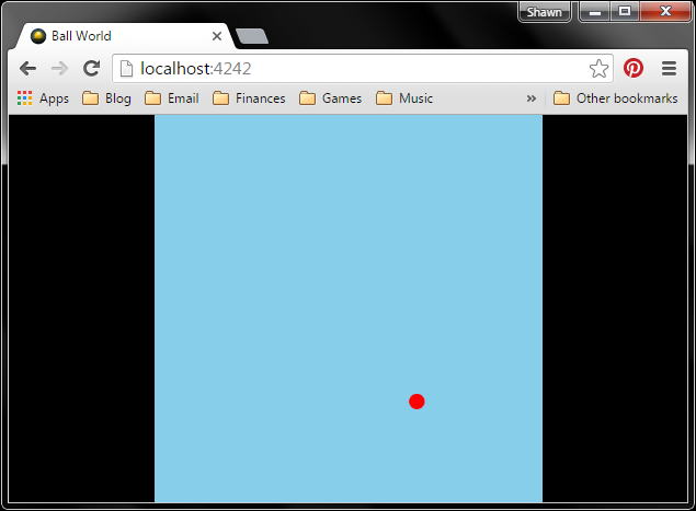
In the last part, we added the Phaser framework to a web page and said “hello” on a canvas element. In this part, we create a simple sprite (a ball) and move it around the canvas.

Why a ball? I consider it to be a test of whether gaming is possible on a particular platform. In the simplest sense, reading user input and moving an object (a filled circle, in this case) shows that real time interactivity is possible. This can be on a computer with a keyboard or on an 8×7 LED array with a joystick.

Directory Structure

In your Games directory, create a new folder named BallWorld. In that directory, create two more directories, js and img. This process should look familiar; the only new thing is that we added an img directory, which is where we’ll store our image files.

Directory structure for BallWorld

Draw a Sprite

There are plenty of ways to create 2D graphics for your game. In these tutorials, we will rely on the free GNU Image Manipulation Program (GIMP) to create sprites. Head to GIMP’s download page and download the latest stable version for your operating system. Run the installer, accepting all the defaults.

Open up GIMP, and select File > New. You will be presented with a new image dialog. Set the Width to 20 and Height to 20. Click on Advanced Options and set Fill with to Transparency.

Creating a new GIMP image

Click OK to create a new image. If you don’t see the Toolbox window, select WindowsToolbox. From the Toolbox, click on the Ellipse Select Tool.

Ellipse select tool in GIMP

Back in your image window, create a circle by dragging a region from one corner to the opposite corner.

Making a circle in GIMP

In the Toolbox, select the Bucket Fill Tool.

GIMP Bucket Fill Tool

Click the color swatch at the bottom of the Toolbox to select a new color. In the Change Foreground Color window, choose the color red (e.g. set the HTML notation to ff0000).

GIMP color selector

Click OK. Click inside the selection circle in the main image window. The circle will fill in with red, and you will notice that some of the pixels around the edge are semi-transparent. This is a technique called antialiasing, which works to make the edges of an image look smoother.

Filled circle

Select File Export As… Save the file as ball.png in …/Projects/Games/BallWorld/img. When prompted, keep the default options in the Export Image as PNG window.

GIMP export image

Click Export. And that’s it! Creating a simple ball sprite is relatively easy. Creating great looking sprites, however, is its own art form. If you are feeling particularly lazy, you are welcome to save the sprite from this image:

Ball sprite

Create the Web Page

In an editor, enter the following:

<!DOCTYPE HTML>
<html>
<head>
    <meta charset="utf-8" />
    <title>Ball World</title>
    <style>
        body {
            margin: 0;
            padding: 0;
            background: #000000;
        }
    </style>
    <script src="js/phaser.min.js"></script>
</head>
<body>
    <script src="js/start.js"></script>
</body>
</html>

Save it as index.html in …/Projects/Games/BallWorld. There are a few difference between the HTML in this example and in the last part.

We change the title to <title>Ball World</title> , which simply updates the name of the page. The name is often displayed in the tab on the browser.

We also add

margin: 0;
padding: 0;

to the body’s CSS. This explicitly sets the margin and padding of the body element to nothing. The body element contains all of the page’s main content. In this case, it holds the Phaser canvas, and by explicitly setting the margin and padding, we can later configure the canvas to fill up the browser window (as much as possible while still maintaining the original aspect ratio).

Additionally, we change the page’s background color to black (#000000 ), which works well for many games, as it mimics a black border or bezel.

Finally, we removed the line <div id=”area”></div> as we want Phaser to just append its own div to the page. By letting Phaser control the div, we can more easily set the canvas to fill up the browser window.

Write Some JavaScript

To install Phaser, copy phaser.min.js from the downloaded Phaser ZIP file to …/Projects/Games/BallWorld/js.

We will write the main game code one piece at a time so we can discuss each section. The code in its entirety will be posted at the end (if you just want to scroll down and copy it).

Create a new text file and start by defining a new Phaser game object. Note that we no longer specify the div parameter as we did in Part 2. By leaving the div id parameter as an empty string, Phaser will automatically create a canvas element and append it to the page’s body.

// Create a new Phaser game object with a single state that has 3 functions
var game = new Phaser.Game(500, 500, Phaser.AUTO, '', {
    preload: preload,
    create: create,
    update: update
});

To this, add the preload() , create() , and update()  functions. For now, leave the functions empty. This is our single-state Phaser template.

// Create a new Phaser game object with a single state that has 3 functions
var game = new Phaser.Game(500, 500, Phaser.AUTO, '', {
    preload: preload,
    create: create,
    update: update
});

// Called first
function preload() {

}

// Called after preload
function create() {

}

// Called once every frame, ideally 60 times per second
function update() {

}

In the create()  function, set the scaleMode  and pageAlign  properties. By setting scaleMode  to SHOW_ALL , the canvas stretches to fill as much of the browser window as possible while maintaining the previously defined proportions (1:1 in this case, as we set the game area to 500×500). By setting pageAlignHorizontally  and pageAlignVertically  to true , we move the game area to the middle of the page.

Stretching the game area and moving it to the middle works as a good compromise for playing games on desktop and mobile devices, regardless of portrait or landscape orientation.

Finally, set the game area’s background color to light blue (#87CEEB ), which contrasts the web page’s black background.

// Create a new Phaser game object with a single state that has 3 functions
var game = new Phaser.Game(500, 500, Phaser.AUTO, '', {
    preload: preload,
    create: create,
    update: update
});

// Called first
function preload() {

}

// Called after preload
function create() {

    // Center game canvas on page
    game.scale.scaleMode = Phaser.ScaleManager.SHOW_ALL;
    game.scale.pageAlignHorizontally = true;
    game.scale.pageAlignVertically = true;
    
    // Change background color
    game.stage.backgroundColor = '#87CEEB';
}

// Called once every frame, ideally 60 times per second
function update() {

}

At this point, you should be able to run the game with:

node SimpleServer.js BallWorld/

Open up a web page, navigate to http://localhost:4242/, and you should be presented with a blue square that stretches to fill up the height or width of the page (whichever is smaller).

Blue background in Phaser

Back in the code, add game.load.image(‘ball’, ‘img/ball.png’) to the preload()  function. We use the game object to load the ball.png image (the one that we made in the Draw a Sprite section) and assign it to the asset label ‘ball’  (also known as a key).

In create() , we add the sprite using game.add.sprite()  and position it at the center of the game area, which can be found with game.world.centerX  and game.world.centerY . We then set the origin of the sprite, using this.ball.anchor.set(0.5, 0.5) , to the middle of the sprite to make it easier to center.

// Create a new Phaser game object with a single state that has 3 functions
var game = new Phaser.Game(500, 500, Phaser.AUTO, '', {
    preload: preload,
    create: create,
    update: update
});

// Called first
function preload() {

    // Load our image assets
    game.load.image('ball', 'img/ball.png');
}

// Called after preload
function create() {

    // Center game canvas on page
    game.scale.scaleMode = Phaser.ScaleManager.SHOW_ALL;
    game.scale.pageAlignHorizontally = true;
    game.scale.pageAlignVertically = true;
    
    // Change background color
    game.stage.backgroundColor = '#87CEEB';

    // Add the ball to the middle of the game area
    this.ball = game.add.sprite(game.world.centerX, game.world.centerY, 'ball');
    this.ball.anchor.set(0.5, 0.5);
}

// Called once every frame, ideally 60 times per second
function update() {

}

Note that after adding the sprite to the game, we assign the sprite object to the variable ball. If we just use var ball , the object would only live within the scope of the create()  function. In order to access the ball object from other functions, like update() , we attach the object to this , which refers to the game state (created as the fifth parameter in new Phaser.Game(…) . Any time we want to access the ball object within this particular game state, we need to use this.ball .

If you refresh the page (assuming the server is still running), you should see a red circle appear in the middle of the game area.

Loading a sprite in Phaser

To move the ball, we need to define a default velocity for the ball (i.e. how many pixels does the ball move each frame) and add some key listeners to the game.

We could hardcode the ball’s velocity, but that’s generally considered bad practice. By keeping all of the game’s parameters in one place, we can tweak the game design without having to hunt down all the hardcoded values. For our purposes, we will define a single global object with the game’s name. This object will hold key/value pairs that set the game’s parameters.

To hold the game’s parameters (we only have 1 right now), create a global object with var BallWorld , and assign it the property velocity: 8 .

In create() , create a keyboard listener using game.input.keyboard.createCursorKeys()  and assign it to this.keys  (another custom game state property).

In the update()  function, we check for specific key presses with this.keys.KEY_NAME.isDown . We can then move the ball’s position using this.ball.x  and this.ball.y .

// Global object to store our game parameters
var BallWorld = {
    velocity: 8
};

// Create a new Phaser game object with a single state that has 3 functions
var game = new Phaser.Game(500, 500, Phaser.AUTO, '', {
    preload: preload,
    create: create,
    update: update
});

// Called first
function preload() {

    // Load our image assets
    game.load.image('ball', 'img/ball.png');
}

// Called after preload
function create() {

    // Center game canvas on page
    game.scale.scaleMode = Phaser.ScaleManager.SHOW_ALL;
    game.scale.pageAlignHorizontally = true;
    game.scale.pageAlignVertically = true;
    
    // Change background color
    game.stage.backgroundColor = '#87CEEB';

    // Add the ball to the middle of the game area
    this.ball = game.add.sprite(game.world.centerX, game.world.centerY, 'ball');
    this.ball.anchor.set(0.5, 0.5);

    // Add key input to the game
    this.keys = game.input.keyboard.createCursorKeys();
}

// Called once every frame, ideally 60 times per second
function update() {

    // Poll the arrow keys to move the ball
    if (this.keys.left.isDown) {
        this.ball.x -= BallWorld.velocity;
    }
    if (this.keys.right.isDown) {
        this.ball.x += BallWorld.velocity;
    }
    if (this.keys.up.isDown) {
        this.ball.y -= BallWorld.velocity;
    }
    if (this.keys.down.isDown) {
        this.ball.y += BallWorld.velocity;
    }
}

Refresh the page again, and use the arrow keys to move the ball.

Key listener in Phaser

You might notice that you are able to drive the ball past the edges of the game area. This is usually not a desirable behavior, so we can add bounds checking on the ball each frame. This is accomplished by setting the ball’s edges’ x and y coordinates to the bound’s edge should the ball pass the boundary.

In update() , add the following:

// Global object to store our game parameters
var BallWorld = {
    velocity: 8
};

// Create a new Phaser game object with a single state that has 3 functions
var game = new Phaser.Game(500, 500, Phaser.AUTO, '', {
    preload: preload,
    create: create,
    update: update
});

// Called first
function preload() {

    // Load our image assets
    game.load.image('ball', 'img/ball.png');
}

// Called after preload
function create() {

    // Center game canvas on page
    game.scale.scaleMode = Phaser.ScaleManager.SHOW_ALL;
    game.scale.pageAlignHorizontally = true;
    game.scale.pageAlignVertically = true;
    
    // Change background color
    game.stage.backgroundColor = '#87CEEB';

    // Add the ball to the middle of the game area
    this.ball = game.add.sprite(game.world.centerX, game.world.centerY, 'ball');
    this.ball.anchor.set(0.5, 0.5);

    // Add key input to the game
    this.keys = game.input.keyboard.createCursorKeys();
}

// Called once every frame, ideally 60 times per second
function update() {

    // Poll the arrow keys to move the ball
    if (this.keys.left.isDown) {
        this.ball.x -= BallWorld.velocity;
    }
    if (this.keys.right.isDown) {
        this.ball.x += BallWorld.velocity;
    }
    if (this.keys.up.isDown) {
        this.ball.y -= BallWorld.velocity;
    }
    if (this.keys.down.isDown) {
        this.ball.y += BallWorld.velocity;
    }

    // Prevent ball from escaping outside the stage's boundaries
    var halfWidth = this.ball.width / 2;
    var halfHeight = this.ball.height / 2;
    if ((this.ball.x - halfWidth) < 0) {
        this.ball.x = halfWidth;
    }
    if ((this.ball.x + halfWidth) > game.width) {
        this.ball.x = game.width - halfWidth;
    }
    if ((this.ball.y - halfHeight) < 0) {
        this.ball.y = halfHeight;
    }
    if ((this.ball.y + halfHeight) > game.height) {
        this.ball.y = game.height - halfHeight;
    }
}

Try refreshing the page one more time, and you should notice that the ball is unable to move outside the game’s boundaries.

Checking game boundaries with Phaser

Conclusion

At this point, you should have the basics for drawing sprites and moving them around the screen. While this is a seemingly simple step, it is an important one for creating the basics of arcade and sprite-based games.


My first Phaser game!

Getting Started with Phaser Part 2: Drawing Text
In the first part, we created a simple web server and page. We didn’t even touch Phaser! However, that is about to change. In the second part of this series, we create a game area in an HTML div and draw some simple text on it using Phaser.

Directory Structure

In your Games directory, create another folder named HelloPhaser. Much like HelloWorld in the previous example, this will house our HTML and JavaScript files for serving the web page and game. Within HelloPhaser, create directory named js. This folder will hold all of our JavaScript.

Directory structure for HelloPhaser

Install Phaser

To install Phaser, we are going to download the library and simply copy it to our js directory. Start by navigating to Phaser’s GitHub page, and click Clone or download followed by Download ZIP.

Download the Phaser library

Once downloaded, unzip the file. Find the unzipped directory, and navigate to phaser-master/phaser-master/build. There, copy the file phaser.min.js. Go back to your Projects directory and paste the file in Games/HelloPhaser/js.

Create the Web Page

Create a new text document and copy in the following (note: I recommend manually typing each line so you get a feel for writing HTML and JavaScript. I’ll talk about what the code does after the code block).

<!DOCTYPE HTML>
<html>
<head>
    <meta charset="utf-8" />
    <title>Hello</title>
    <style>
        body {
            background: #FFFFFF;
        }
    </style>
    <script src="js/phaser.min.js"></script>
</head>
<body>
    <div id="area"></div>
    <script src="js/start.js"></script>
</body>
</html>

Save the document as index.html in Games/HelloPhaser.

This file acts as our basic web page. Its primary purpose is to set up a game area (div) on the page and load in JavaScript. The JavaScript handles the bulk of the drawing in the game area.

In the <head> section, we use some simple CSS via the background property to set the web page’s background color to white (#FFFFFF). See this table for colors and their hexadecimal codes. We also load in the Phaser library using the <script> tag.

In <body>, we define a <div> and name it “area.” We will reference this div later in our JavaScript code and draw Phaser objects in it. Finally, we load in another script, named “start.js,” which is where our main game code will live. We have not written start.js yet; that comes next.

Write Some JavaScript

Create a file and copy in:

// Create a new Phaser game object with a single state that has 3 functions
var game = new Phaser.Game(500, 500, Phaser.AUTO, 'area', {
    preload: preload,
    create: create,
    update: update
});

// Called first
function preload() {
}

// Called after preload
function create() {
    
    // Create some text in the middle of the game area
    var helloText = game.add.text(250, 250, 'Hello, Phaser!', { 
        fontSize: '32px', 
        fill: '#00F' 
    });
    helloText.anchor.set(0.5, 0.5);
}

// Called once every frame, ideally 60 times per second
function update() {
}

Save the file as start.js in Games/HelloPhaser/js.

At this point, you should have index.html in your page’s directory (HelloPhaser). Under the js directory in HelloPhaser, you should have phaser.min.js and start.js.

Files in HelloPhaser

Let’s look at what the code is doing. In the very first line (after the //… comment), we create a Phaser.Game  object and assign it to the the variable game . Phaser.Game is predefined in the Phaser library (documentation on it can be found here), and it is the core of the Phaser framework.

The first two parameters for Game  define the resolution of the game area. In this case, we set it to 500 pixels wide and 500 pixels high. I’m a big fan of square game areas, as it works well on desktop and mobile devices without needing to skew the graphics when switching between portrait and landscape modes. Feel free to change it for your application, though.

The next parameter, Phaser.AUTO, sets the renderer for the game area. As of the time of this blog post, there are three types available:

  • Phaser.CANVAS – Canvas element for drawing 2D graphics. Canvas is supported on most modern browsers.
  • Phaser.WEBGL – Use hardware-accelerated graphics to draw on the canvas. Some browsers support WebGL, and the user’s device must have the requisite hardware. 3D graphics are possible with WebGL.
  • Phaser.HEADLESS – Do not use any renderer. This is useful when you don’t want any graphics (such as running a game server).

In general, Phaser.AUTO is advisable, as it initially tries to use WEBGL and if the browser does not support it, the renderer reverts back to CANVAS.

The fourth parameter, ‘area’, tells the Game object where to draw. In this case, it is creating a canvas inside the div named ‘area’ (remember how we created a <div> element with the id “area” in our HTML?). If you leave this parameter blank, Phaser will simply append the Game object to the page.

The fifth parameter is the initial game state. If this parameter is set, Phaser will immediately start running the functions in this state. Note that Phaser supports multiple states in a game, and these can be things like start screen, game play, game over screen, menus, etc. For now, we will only use one state. Examining this state object, we see:

{
    preload: preload,
    create: create,
    update: update
}

Phaser states have a number of reserved names for functions. We are using preload , create , and update . We assign the functions (similarly named preload, create, and update) to the specially named keys, which are defined by Phaser.

The state will first run preload() , which is generally where assets like sprites and sounds are loaded. Since we don’t have any assets, the function is left blank. The function is still explicitly written here for the sake of clarity; we will add code to it later.

Second, the state will automatically run the create()  function once the preload has finished. This is where you can draw sprites, text, add key handlers, and so on. We add a single line of text, “Hello, Phaser!” to the game area, set at (250, 250), which is the middle of the area. We set the text’s anchor to (0.5, 0.5), which changes the origin point for the text to its center. For anchors, (0, 0) is the top left, and (1, 1) is the bottom right.

Finally, we define the update()  function. This function is automatically called every frame, and it is where we would put things like input polling, checking for collisions, etc. Because our “game” is just static text right now, there is no need to have anything happen in the update function.

Run It!

Open up a command prompt, navigate to your Games directory, and run the server (note that we need to specify HelloPhaser as our web page directory):

cd <PATH_TO_PROJECTS>/Games
node SimpleServer.js HelloPhaser/

Open up a web browser and navigate to http://localhost:4242. You should see your game (albeit a rather boring game):

My first Phaser game!

You can’t do much with this game, as we have not added any type of input handling or graphics updating. That will come next.

Conclusion

While it was not much of a game, we did use the Phaser framework to create some text in a canvas element, which is a huge step! This template (index.html, phaser.min.js, and start.js) will form the basis for future tutorials. You can simply copy phaser.min.js into your other games, although I recommend checking Phaser’s GitHub page for updates regularly.

If you are new to JavaScript, I highly recommend working through some chapters in the book Eloquent JavaScript (it is the book I used to teach myself JavaScript). The book is available online for free as well as in paperback copy on Amazon.

Continue to Part 3 to learn how to create sprites and add movement with key presses.

Phaser logo

Getting Started with Phaser Part 1: Web Server

As I learn to use the Phaser framework to make simple browser-based games, I figured I would chronicle my adventures and hopefully help others out.

“Why a web web server?” As it turns out, when most browsers run a page as a local file, it locks down access to many other files, which we need for our games. To read more about this, see this article.

To properly serve these files, we can use any number of existing web server software, but we will write a simple one using the Express framework in Node.js. In the future, we can modify this simple server to receive information back from our game to do things like control hardware and *gasp* make multiplayer games.

Install Node.js

Navigate to the Node.js download page and choose the installer for your operating system. Run it, and accept all the defaults to install Node.js on your computer.

If you are using Linux, most package managers can install it for your. For Debian, try apt-get install nodejs npm . For other distros, see this page.

If you are weird like me and enjoy the Linux command line but work in Windows, I highly recommend installing Git Bash through the Windows git installer. We’ll need to use git later, as GitHub allows us to host our projects for free. All of my command line screenshots will be from Git Bash.

Install a Text Editor

For these simple programs, we’ll use a basic text editor to write our code. If you haven’t already, install the text editor of your choice. You can use Notepad, but I’ll make a few recommendations for programming-focused editors:

Directory Structure

Create a folder named Games in a place where you like to keep your projects (e.g. My Documents/Projects). In Games, create another folder named HelloWorld.

Directory structure for our game server

The goal is to create a web server that lives in Games. Whenever we want to test a game, we run the server with Node.js and pass it the folder (as an argument) of the desired web site (e.g. “HelloWorld”).

A web site, in a practical sense, is just a collection of files on a computer that get served to a client upon request. For us, each project folder under Games will be its own site, and we just point our simple server to that folder in order to host the site.

Install Express.js

Express.js is a web application framework made for doing, well, lots of web stuff in Node.js. For our purposes, we are going to use it to make a simple web server that just serves files when asked (via HTTP requests). We could write our own server using the http module, but Express.js just makes things easier.

Open up a command prompt (e.g. Git Bash), navigate to your Games directory, and install Express.

cd <PATH_TO_PROJECTS>/Games
npm install express

You might notice that this creates a directory named node_modules in Games. This is where Node.js modules, like Express, are stored.

When you execute node and it attempts to load a module (i.e. through the require() instruction), Node.js first looks in the current directory for a folder named node_modules. If a module with the name in require() is not found, it begins to work its way up directories looking for node_modules. If the module is not found at all, the require() command will throw an error, and your program will fail.

Write the Server Code

Open up your text editor and copy in the code:

/**
 * Simple web server based on 
 * http://expressjs.com/en/starter/hello-world.html
 *
 * Prerequisites:
 *  - Node
 *  - Express (npm install express)
 * 
 * To use, save as a file (e.g. SimpleServer.js) and run with:
 *  node SimpleServer.js /PATH/TO/WWW/
 */
 
// Parameters
var sitePath = process.argv[2] || ".";
var port = 4242;

// Libraries
var express = require('express');
var app = express();

// Request logging
app.use(function(req, res, next) {
    console.log(req.url);
    next();
});

// Start server
console.log(sitePath);
console.log("Starting server in: " + __dirname + '/' + sitePath);
app.use(express.static(__dirname + '/' + sitePath));
app.listen(port, function() { 
    console.log("Server running at: http://localhost:" + port)
});

That’s right, in about 15 lines of actual code, we have a functioning web server. Neat. In all honesty, though, Express is doing most of the heavy lifting for us.

Save the file as SimpleServer.js in the Games directory.

Create a Simple Web Site

Our site will be a single page with a title and some text in the body. In later parts, we will add a Canvas element and begin using Phaser to create games.

Create a new text document in your editor and copy in the following:

<!DOCTYPE HTML>
<html>
<head>
    <meta charset="utf-8" />
    <title>My Page</title>
</head>
<body>
    <h1>Hello, world</h1>
    <p>This is my page. There are many like it, but this one is mine.</p>
</body>
</html>

Save it as index.html in Games/HelloWorld. At this point, your directory structure in <PATH_TO_PROJECTS>/Games should look like this:

Games directory tree


Run the Server

In your command prompt, navigate to the Games directory and run the server, specifying the HelloWorld directory as the root for your web site.

cd <PATH_TO_PROJECTS>/Games
node SimpleServer.js HelloWorld/

If all goes well, you should see a note appear in the console that the server is running at http://localhost:4242.

Running a simple server

Open up a web browser and navigate to http://localhost:4242. You should see your page.

My first page

If you look at the console, you’ll see that a ‘/’ has appeared.

Console showing HTTP request

This means that a client requested the website’s root directory (‘/’). The server responded by sending index.html as a result, which is the default file for most websites. In this case, the root directory is HelloWorld, as we specified when we started the server.

Conclusion

We did not even touch Phaser in this part. Crazy, I know, but we needed to create a basic structure for hosting our games before we can even make them. Such are the joys of browser-based games.

If you aren’t familiar with HTML, now is a good time to play with the web page, index.html. We won’t actually do too much in HTML, but it’s good to be familiar with how tags, loading files from source, and a little bit of CSS work. Geek Champ has a great getting started with HTML tutorial.

When you are ready, continue to Part 2.

Adding 2 drill holes

Getting Started with EasyEDA Part 1: Part Creation
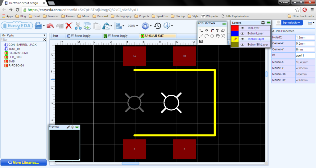
Introduction

Free, online development and CAD tools are becoming more popular and powerful, and PCB layout tools are no exception. In this, we are going to look at how to create a simple schematic in EasyEDA, turn it into a PCB, and send out the design files to a PCB house for fabrication.

We will do this in several parts–starting with part creation, then schematic capture, and PCB layout before sending out files for board fabrication. By the end, we’ll have made a simple linear regulator that supplies 5V and up to 1A to a breadboard and accepts a barrel jack from a wall adapter to provide power.

Signing Up

Head to easyeda.com, and click Login at the top of the page. While you can start without an account, being able to save projects to your account is quite useful.

Register for an account

Fill out your information and click Register.

Continue Reading
Cross compile for Edison

Cross Compiling on Linux for the Edison
Cross compile for Edison

Since I had a couple requests on how to cross-compile C/C++ programs for the Edison, I figured a quick post wouldn’t hurt. Note that I am using Ubuntu 14.04 (64-bit) for this example.

Download “SDK – Cross Compile Tools” from https://software.intel.com/en-us/iot/hardware/edison/downloads.

Unzip and run the installer. Note that the name of the files may change depending on the version of the SDK and your operating system.

Continue Reading
Edison Base Block

Run a Script on Edison Boot

Edison Base Block

Image courtesy of sparkfun.com

This one took me forever to figure out, and thanks to some posts over at the Intel Edison forums, I finally managed to get a JavaScript program to run as soon as the Edison starts. I know that the XDK also runs a service to execute JavaScript programs on boot, but I wanted a more general solution. One could configure the systemd service file to run any program/script on boot (assuming the Edison has the right interpreter).

Continue Reading

Writing Your Own UPM Module: Getting Started

Intel-IoT_LogoImage courtesy of Intel iot-devkit GitHub account

UPM (Useful Packages and Modules) is a high-level library that relies on MRAA to talk to hardware peripherals over GPIO, SPI, UART, etc. Both libraries were created by Intel and come packaged with the Galileo and Edison boards. MRAA has support for other single board computers, like the Raspberry Pi and Beaglebone Black, according to the MRAA documentation.

MRAA is the low-level driver that controls the individual bits for the GPIO. UPM is a collection of libraries (modules) that provides the necessary software for various sensors, motor drivers, etc.

Continue Reading

Creating a Custom Linux Kernel for the Edison (release 2.1)
In this post, I will go over how to create a custom Linux image for the Intel Edison using the Yocto Project Edison source code release 2.1.

Intel Edison_and_Pi_Block

Apparently, it’s been almost exactly a year since I originally posted how to create a custom Linux kernel. Weird.

Well, since that time, I’ve had some people ask about updating that tutorial, as a few steps no longer apply and the whole thing is out of date. It seems that the Yocto Project also grows and changes over the months.

I created this tutorial with the help of the Yocto Project Getting Started Guide, the Intel Edison Board Support Package, and this thread on the Intel forums.

A few notes before we get started:

  • All of these steps are performed on a Linux host machine. I recommend Ubuntu (or another Debian distribution), as I use apt-get liberally.
  • You will need at least 50 GB of free hard drive space. The Yocto Project can be quite large.
  • The hard drive should be a Linux partition (e.g. Ext4). Trying to execute some of the scripts from an NTFS drive proved difficult.
Continue Reading
Edison with wires!

Bluetooth Low Energy Peripherals with JavaScript
Edison with wires!

Previously, I’ve shown how to enable Bluetooth Low Energy (BLE) connections using Python. In the past few months, I have been furiously learning JavaScript for an upcoming set of tutorials dealing with the Intel® Edison. Along the way, I needed to make a demo using BLE and JavaScript, which invariably led me to the bleno module.

Bleno is a great tool, but I found some of the examples a little confusing to follow (I get easily lost when a program is split into more than 2 files without a well-documented API). As a result, I constructed a simple echo server demo program that illustrates how characteristics work in BLE.

Continue Reading
SparkFun ESP8266 Thing

Quick Tip: HTTP GET with the ESP8266 Thing
The SparkFun ESP8266 “Thing” is one of the cheapest Internet of Things (IoT) platforms available.

SparkFun ESP8266 Thing
Photo courtesy of sparkfun.com

There are some great examples on how to post data to data.sparkfun.com, but we need to modify that code in order to pull data from a website. That is accomplished with the humble HTTP GET request. I put together a quick example that pulls www.example.com and prints it to the serial console. Note that you will need perform some slight modifications to the board (or use Realterm) to see the serial data.

Continue Reading
Teensy LC input capture test

Learning the Teensy LC: Input Capture

Teensy LC input capture test

As a third step to learning the Teensy LC, I decided to tackle input capture. I discovered that there is no separate interrupt vector for input capture; it is the same vector used by the timer interrupt. This means that if we are looking for a timer overflow event as well as a pin change for input capture, we must check for that specific interrupt flag within the interrupt service routine (ISR).

Continue Reading
Custom ISR in the Teensy LC

Learning the Teensy LC: Interrupt Service Routines
Custom ISR in the Teensy LC

As a follow-on to my PWM experiments, I wanted to create a custom interrupt service routine (ISR) in the Teensy LC. This would be similar to using the ISR() macro in an ATmega-based Arduino. Because the ARM has different vectors (and some other weird/cool things, like configurable interrupt priority levels), I knew the normal ATmega vectors would not work. Luckily, PJRC created a set of vectors to work with the Teensy, which can be found in this code.

You don’t need any additional components for this example. We are just going to flash the on-board LED using our custom ISR.

Continue Reading
Edison and RFduino

Using Python and BLE to Receive Data from the RFduino
Edison and RFduino

It’s should be no surprise that I enjoy working with the Edison. It may not be as easy to work with as the Raspberry Pi, but I still like it.

My current project includes getting the Edison to talk Bluetooth Low Energy (BLE) to another device. The RFduino is the device in question, as I should be able to receive data as well as control peripherals attached to the RFduino. The final project will be an addition to the IoT YouTube series that I am working on (at SparkFun). I’m not spoiling anything!

Continue Reading